0. Foreword
Please, do not post elsewhere the code found here.
– The code should reside in one place and people should use links to my site instead. I have a hard time browsing the Internet for pieces of code sometimes, and finding old or obsolete code instead of links to the original developer is always a pain in the ass.
– I expect people to comment on the code and make optimizations/new developments, especially for student usage. Having this in mind, the code itself is an ongoing process which can be followed by students, from its first state (intelligible, but unoptimized) to its latest state (optimized, but unintelligible). Many people asked me how the code becomes awful and almost impossible to understand. It is my chance to show that I always start from a human approach and I am ending to a computer approach, and that this is always an endeavour that takes time and patience and endless computations and verifications, it doesn’t just come from thin air.
– the last reason is that I collect stats on page visits and downloads, which show me where to insist with open source development and where not to. I cannot collect stats from foreign sites, nor do I wish or have the time to do so.
Thank you!
1. Introduction
I have bought 3 pieces of SKU14220 – DIY 4 Digit LED Electronic Clock Kit Large Screen Red Blue Green LED from banggood. At ~ US$12, it seemed a good deal and most interesting. Following my experience with the EC1204B clock, I was almost sure the firmware was going to be bad.
Bad is a nice thing to say. The firmware was horrible:
– it doesn’t show day/month/year;
– the setup is tricky and not easy to remember/understand;
– it lacks temperature;
– many people comment it is too bright during the night.
– the STC 15F204EA processor was a bad choice. 4K of flash do not suffice to build a nice and comfortable firmware for the end user, in my experience this design needs an processor with at least 8k flash.
So I decided to modify the latest firmware for the EC1204B clock and make it available for this version, with the necessary modifications.
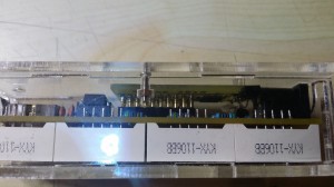 Figure 1 – SKU142210 clock assembled – bottom view
Figure 2 – SKU142210 clock assembled – top view
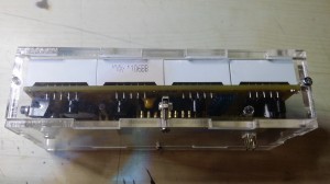
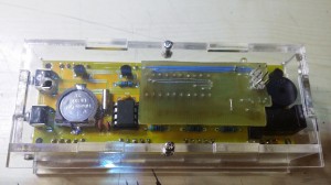 Figure 3 – SKU142210 clock assembled – rear view
Disclaimer:
The software/firmware presented here is a complete rewrite from scratch, just by observing the schematic and by understanding the way it works. It did not involve any kind of disassembly of the original firmware, reverse engineering or other similar stuff.
I do not condone copying the work of others in any way. However, progress is difficult to achieve these days from zero and it is easier to build up on something that already exists, while respecting the original work and effort.
I advice my readers to buy Banggood kits, the PCB has an excellent quality and all the parts delivered will be used, even with the modifications I suggest in this post. The idea is to start learning soldering and coding using affordable ressources.
2. Hardware modifications
Video 1: The modified clock
After studying the schematic, it became obvious the only thing that needed to be replaced was the processor itself, with another firmware.
I couldn’t find any Atmel processor compatible pin to pin with the original, STC 15F204EA processor. The available place to insert a custom PCB in the processor’s slot is also narrow, so space would be of the essence in choosing a replacement processor.
This is why I have decided to use an ATmega8 AU, which is the smd version of the ATmega8.
Supplementary, a DS18B20 was added to measure temperature along with a photo-transistor, to implement automatic dimming of the display.
From a mechanical point of view, the programming pins were designed to go through the plexiglass wall, in order to allow programming of the device even when it is fully enclosed, without the need to disassemble the enclosure (see Figure 3 above).
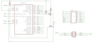
2.1 Schematic
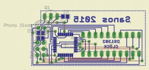
2.2 PCB
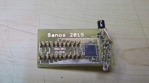
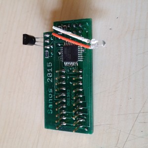
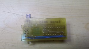
2.3 The actual PCB
Figure 5. The bottom side of the PCB
Figure 6. The top side of the PCB
3 Software-firmware
The software, or firmware, is a variation of the software used for the EC1204B clock, in a previous post of mine.
Disregarding the process of eliminating pieces of code that did not apply to this particular clock, the two main additions are:
-the implementation of analog reading from a photo-diode, quite straightforward process;
– the implementation of digital dimming a multiplexed display.
A few words about the latter. The problem was to dim the display without having disturbing light shifts.
How it was done: In a multiplexed display, only one digit is lit a a time, with the specific data for that digit. Then, we go to the second digit and so on until the last. Basically we have an eternal cycle of lighting each digit at a time, cycle equal to the number of digits to be lit. What if we would add to this cycle “dead” times, when we don’t lit any digit? The result will be a software pwm on the multiplexed digits, up to the point when all the digits start to tremble. After a few trials, I have discovered that this has to stop at around 50 cycles. After 50 cycles, the dimming process isn’t perceived by the human eye, but it inserts this trembling of the digits.
The relationship between the level of light and the dimming is a simple transformation of the first degree, where dimming is inversely proportional to the level of light. The actual parameters are decided by experimenting. In this particular case, I had:
0 light -> 50 dimming cycles
50 light -> 4 dimming cycles.
The transformation became : cycles = (54-light), which is a rough approximation of the hypothesis above. A supplementary condition is also in effect, after reading the light value:
if (light>50) light=50;
This was necessary from direct observation: at 50 light, the display was too dimmed and the light value (0-100) didn’t correspond well with the dimming if it was to be used full scale.
Feel free to play with the code and try to modify and optimize it. I hope it is easy enough to understand after 1-2 hours of study, in its most intimate details.
4. How it works
The upper button is the “set” button. The lower button is the “select” button.
- Pressing the Set button will cycle between the DS18B20 temperature sensors present at start up. On the board there is only one sensor, but you may solder several other sensors, all connected in parallel, and the device detects them at start up.
- Pressing the Select button will enable you to program the microcontroller:
- A short press (less than 5s) will show the date and month. Pressing it again will show the year. One more press reverts to clock display.
- A longer press (6-10s) will enter the alarm set mode. Press set to cycle between alarm hour, minutes, alarm enable and memory storage. Press select at each stage to cycle possible values (0-23 for hours, 0-59 for minutes, on/off for enable);
- A longer press (11-15s) will enter the clock set mode. Press set to cycle between year, month, day, minutes, hours and memory storage. Press select at each stage to cycle possible values;
- A longer press (16-20s) will enter display mode. Press set to cycle between on, off and memory storage. Press select at each stage to cycle possible values;
- A longer press (21-25s) will enter the temperature unit select mode. Press set to cycle between C,F and memory storage. Press select at each stage to cycle possible values;
At each stage, the last select key press is the memory storage. After storing selected parameters, the clock will beep. If you fail to store parameters (i.e. you do not press the button), the parameters will be in effect until the next reset of the clock.
5. Download
All the project for Atmel Studio 4, including a PDF with the PCB printout and necessary datasheets for parts (DS1302, DS18B20) can be downloaded here.
Following Bob Pike’s request to have the firmware show temperatures in F instead of C, the code was modified with the possibility to program the temperature display unit. The latest version can be downloaded here.
Last edit: 18.04.2015
6. Semi-automatic software drift compensation
Many people (including me) complain about the DS1302 drift, related to badly manufactured quartz resonators that do not offer a real 32 kHz (32768 Hz) clock.
The drift may become so big, a clock can have easily +- 10 minutes drift in a matter of months. Having two or more clocks in different rooms may easily lead to headaches in the morning when the decision to leave for work becomes a growing pain week after week.
The best practice would be to insert a trimmer capacitor in series with the quartz and set it to obtain a 32768 Hz clock. Even this practice is prone to errors due to:
– bringing a metallic screwdriver next to the trimmer alters its capacity. After setting the trimmer it would change its capacity again, hence the clock;
– normal trimmers are influenced by temperature. Just a little, but enough to generate a 1-minute drift every month or so;
– usually there is no or very little space on the PCB to insert a trimmer properly;
– the DS1302 clock could stop if a trimmer inserted in the circuit.
I have imagined a software solution to the drift, by calculating it in between two clock settings.
I began by asking myself what would be a disturbing drift, and I came with 5 minutes per year at a minimum, as being disturbing. However, setting the clock every year wouldn’t be too much to do, since I already set the clock twice a year when the daylight saving time appears and disappears.
5 minutes per year would mean a drift of roughly 5*60/12=25 seconds a month, less than 1 second per day.
Since the setting is done manually and one could press the set button with a 1 second drift, if the setting would be done after 20 days, it would lead to a supplementary error drift of 365/20=18.25 seconds a year, which is less than a minute per year: it wouldn’t even be noticeable.
The whole idea is to set the clock twice in the same month from a good time source (like your PC, after synchronizing its time with a time server). Why during the same month? Just to make the subroutine that computes time difference easier and less flash consuming. Anyway, there’s less than 1K of flash available for this with this project.
So: you set the clock on the 1st of the month and then you set it again on the 20th or 30th of the month.
The software computes the time difference from the two settings, which were made using a good time source and it will also compute the time difference the DS1302 has run, thus determining the time drift in a given period of time (let’s say 34 seconds in 28 days).
28 days equal 28*24*60=40320 seconds
So we have a drift of 34 seconds every 40320 seconds, which means a drift of 1 second every 1185(.88) seconds.
The clock will remember this drift and the processor will either add or subtract (depending on whether the drift is positive or negative) one second every 1185 seconds, by reading and rewriting the seconds in the DS1302.
Two errors are now in place:
– a 0.88 second (from rounding 1185.88 to 1185) every 40320 seconds, leading to roughly 12 seconds a year: almost non existent;
– a supplementary error drift from manipulation of the setting button of 365/20=18.25 seconds a year: almost non existent either;
In fact, this kind of semi-automatic drift compensation can lead to an error of at most 30 seconds a year, much lower than we could obtain by inserting a trimmer and setting it to achieve a 32kHz clock for the DS1302. We would experience annoying drifts in 10 years of non-stop operation of the clock.
What if we set the clock in different months? The software compares the month and the year of the last setting and the previous one. If these do not match, the clock drift is set to zero and there is no automatic drift compensation. A new clock setting in the same month would trigger a new drift computation and automatic drift compensation.
What if we set the time more than once during the same month? The software would take into consideration the last interval between two settings. If the interval is too low (e.g. 3 days) it could lead to a wrong computation of the drift compensation.
In order to set the drift compensation to zero, please operate two consecutive settings one after the other or by changing the month or year.
This version of the firmware can be downloaded here.
7. Bug fixes, additions and optimizations
While working on my other project, the EC1204B Led rotating clock and implementing some requests from my readers, I have discovered ways to improve the code and also minor bugs that were addressed.
- the code to multiplex the data on the display was optimized;
- there was a bug while displaying temperatures over 100. It was fixed.
- the colon display was modified. Now the colon displays whenever a second starts instead of displaying it on odd seconds only.
- Peter Casper had a request to alternatively show the clock and the temperature, for he wishes to use the clock in an infrared-heated room.I thought using the same idea as above, so a new EEMEM variable was defined and if at programming time it is equal to 1, it fires a condition in the main loop that shows the temperature for 1 second every 10 seconds. It displays just with one (or the first) temperature sensor.Some optimizations to the display routine were also made.Because this firmware is about to hit the available flash memory in the mega8515, I had to look closely of the size of the binary data that was about to be burned into the MCU. How to do this, since the HEX file size has nothing to do with the size of the binary code? I have written this morning a Windows tool that converts Intel HEX files to binary and viceversa + it allows for automation…well, silent repetition of a load and save operations. I know, I am lazy, that’s why I wished for automation. Find what it is all about in this post.This version of the firmware can be downloaded here.
8. Combining all latest developments in one and allowing for setup without the need to reprogram the flash
While working on the latest requests for US mode (12H display and Fahnrenheit instead of Celsius), I used EEPROM variables to shorten the code and allow for its implementation. Unfortunately, to change these modes, the clock needed to be reprogrammed.
After many optimizations, I have succeeded to implement a way to set these modes without the need for a programmer.
Toggle between US and EU mode is now done from the menu itself:
- EU mode displays 24H and Celsius. Setting the clock and alarm shows 24H.
- US mode displays 12H and Fahnrenheit. Setting the clock and alarm shows 12H with A or P indicator for AM/PM.
Resetting the clock while pressing the SET key will toggle between regular clock display and clock/temperature display (temperature is displayes for 1 second every 10 seconds).
Enjoy downloading the latest firmware, datasheets etc, here.
At this moment, the firmware has 8160 bytes, further development on this firware being almost impossible, at least with the ATmega8.
9. It becomes a never ending story, huh?
Following the latest developments on the EC1204B clock, a new set of improvements to the code were added:
- the code was optimized, again, to lower its size;
- the ghost digit disappeared;
- the clock can measure now negative temperatures on both C and F;
- toggling between EU and US modes may also be done by keeping SET pressed at startup. It can also be changed from the menu.
Enjoy downloading the latest firmware, datasheets etc, here.
Last edited 17/01/2017
50 Comments
Cristian, I enjoyed seeing your write up on putting new firmware in the Banggood led clock. I’m 55yr and have found I really enjoy putting these types of kits together as I had done in my teens. I can’t program or etch my own circlet boards but sitting down and putting this type of kit together (AND having it work) is still very for filling to me. I wish I could get your PCB for my clock but I live in Florida USA and can’t just drop in to see you LOL. I was also curious how much it cost to make it (if you can tell me in US dollars I would appreciate it)? Thanks again for the write up and video. Bobb
If you wrote me in January, I could have brought you one. I was in Miami for a couple of days 🙂
I’m gonna make another three pieces because I have some kits laying on my table for a while. I’ll make one for you too and send it in a small package, probably by the end of the month. Please send me your postal address by email. There’s no cost involved in manufacturing it, I am always happy to help a fellow. The parts themselves are somewhere around $10, so you might as well send me back a couple of american beers I had never had the chance to enjoy!
Following our email exchange, the firmware now knows to toggle temperature units display, between C and F.
Hi Cristian ,
You did a good job with this update ! Thanks for sharing your experience and your work with us.
I would also like to make this change,but I have problems with the flashe of Atmega8.
I use AVR_DUDE program and because of this I need fusebits settings.
Please send me the fusebit settings, so I can right flash the CPU.
Thanks so much for your understanding and further successes !
Friendly regards from Sibiu, Romania – Viorel
Here are the fuse setting for the atmega8 used in the system.
Thank You Cristian ! I’ll keep you achieve the circuit.Have a nice Day ! Viorel
Please do keep me posted. I wish to have real testimonials instead of fake ones.
Whatever your experience may be , pro or con, please post it here.
Hi Cristian
I’ve just finished building the clock and I read your modification write up. I would really like to do the same to mine but unfortunately I just don’t have the resources to manufacture a pcb or even program the ATmega8 AU. Is there any possibility that you could supply these 2 items or even the whole kit. I will gladly pay whatever the cost as I find these projects keep me occupied in my retirement. Thank you so much.
Rob
Hello Christian!
I’ve ordered this clock a week ago, and it arrived today! I thought it would be a bit larger, but
everything beside, I think this thing is awesome!
A question: can’t you buy a STC 15F204EA?
And then flash your source in the new one? Or am I seeing something wrong here?
But if buying a STC chip doesn’t work, then your idea of making a board that fits the socket of the cpu, is the way to go! But, uhum, why not put a couple of sensors on the new board too? 😛
Greetings Marjon
Holland
I’m fairly new to microprocessors, fpga and stuff like that, so I don’t know everything.
Hi Marjon,
You don’t just flash the source, you flash the compiled binary.
To accomplish this, one would need to learn the processor, rewrite the program specifically for that processor (timers, timings, etc – basically the whole internal stuff), compile it in a IDE specific for that processor etc.
This would be feasible in a certain amount of time, but:
As far as I have seen, there are no pins left of the original processor, so there’s no way to put the two sensors on it. That’s why the new processor is needed, with more I/O pins to link the sensors to – including an analog pin for the light sensor.
Cristian
Cristian;
I’m looking at, using an Atmega328 Arduino Compatible board, that I currently have on order, from Hong Kong (It’s currently listed on EBay as “Pro Mini atmega328 5V 16M Replace ATmega128 Arduino Compatible Nano F5 Board”, They cost about 2 U.S. dollars each, if U buy 5, I plan on wiring up, an umbilical cord, from this little board, to a 20 pin socket that will plug into the clock’s board. I plan on using the same IO pin setup, (To start with), that U did). It looks to me that, this board should work, after removing the crystal and its 2 capacitors, to free up those 2 IO pins and then maybe change some of the pull-up resistors around on the Atmega328 board, after I’m able to look at the board
Do U think, your compiled code, will run, on an Atmega328 processor, like it is, or will it be necessary, for me, to make changes to your code, before recompiling it, to run on an Atmega328 or do U think, that just recompiling, your source code, as it is, to run on an Atmega328. That it, will be able, to load and run, after the recompile?
I’m, also, thinking about trying to configure, 2 IO pins, on the Atmega328 Board, to be used as, serial IO, that can be used as a USB port, with the use of the same, little plugin USB adapter board that is used, to program the Atmega328 Board.
I hope to be able to setup and read, the DS1302 clock chip, from a PCs USB port. I don’t care, if the clocks LEDs, need to be blanked (LED driver updates suspended), while using a slow serial rate, like 2400 baud, to be used for the serial IO. (It looks like 2400 baud, is the only baud rate, that is close enough, to work, with the processor’s onboard USART, because of the processor’s speed, being 8Mhz.)
I’m much more comfortable, with Assembly Language, than with “C”, so it’s going to be a real uphill battle, for me, to do this.
But, as they say, “No Pain, No Gain”.
I was wondering, which U would suggest, as being the best way to try, swapping the processor’s 2 IO pins (PD0(RXD) & PD1(TXD) and then use the onboard USART), these 2 pins are currently being used to drive LED Segments A & B, of the clocks LED Display, with the 2 IO pins (PB4 & PB5), that are currently being used to read the clocks switches S1 & S2, (and then fix-up the source code, for these changes,) or to not swap any IO pins, and then setup a “Bit-Banging software UART” using pins (PB4 & PB5), so the same 2 IO pins, can be used for serial IO and also, still be used to read the clock’s switches S1 & S2.
I also wonder, if maybe the processor’s onboard USART, could also use the 2 pins (PD0(RXD) & PD1(TXD)) for serial IO, while the same 2 pins are still corrected to A & B segments of the LEDs, while the LED Display is being Blanked (because of the need to suspend the LED driver updates while using the onboard USART pins).
Any suggestions with these changes would be appreciated.
Thanks for making the source code available.
If, I’m able to make this, all play, I plan on doing the same.
Thanks
Tom
Hi Tom,
quite a long message.
1. Arduino nano:
– it will not fit in the plexiglass case;
– it would need another board with the sensors and pullup resistors. So why not build the board I have designed specifically for the project?
– it uses C++ instead of C. Translating the program would be a nightmare. As well you should make a complete rewrite, it would be faster.
– it communicates serially with the mega328, where there is a bootloader already flashed, which takes the compiled program from the arduino ide and flashes it internally into the program zone. any other use of the USART is pointless.
From my point of view, arduino won’t do here.
2. Why in a million years would you read the DS1302 with a PC? Excepting the fact that it is not serial, almost impossible to link to an usb without a separate MCU, the main idea is to have an automaton do this: the clock itself.
3. Pins: you can use any pin you wish, they are all digital, except the pin for the light sensor, which must belong to an ADC port. However, there are differences in reading from a mega8 and a mega328: values are different and the polynomial transformation must be adapted properly.
4. Modifying the processor itself: there are a number of things that has to be taken into consideration. An extensive reading of both mega8 and mega328 data sheets is advised. Programming the timers, initial programming of the ports, programming the ADC port and pin as well as reading the analog values, programming of the fuses…all these require extensive experience with atmel MCUs. This would lead in a lot of modifications on the source code.
This firmware is already an adaptation of one of my previous firmware written for an ATmega8515. It took me one full day (16 hours of work) just to adapt the basic functions and make them work. And I’ve written tons of firmwares. So…
Cristian
Cristian
Thanks for taking the Time to Reply!
This little Pro Mini atmega328 Arduino Compatible board looks to be about 1.3 x .7 inches. It would be tight, but there should be room to fit in the clocks case.
It looks to be, just a little brake-out board, with an ATmega328 & a Voltage Regulator, with a Bootloader on it. Most of the processor’s pins are brought out to pads around the board’s edges.
I was going to add, the few needed parts, onto pads around the edge of the brake-out board.
I had hoped, that this little, board could be used with little or no changes to your source code. I have been looking, at your code, and there is a lot for me to understand about, what all, is going on (Good job!) !!
I will forget the use of the UART.
I agree (with U) that, I’m in over my head about programming it in C++!!
Thks, Again, for your article and releasing the source code.
Tom
Tom,
I have also bought, for fun, some arduino nano boards, probably the same you have bought too.
On the board, there is a 6-pin connector you can use to program it with a regular atmel programmer (an STK500, MK2 etc).
This allows for flashing a compiled program, written with ANY programming IDE in no matter what programming language.
Just for educational purposes, you might try to do this, you will learn a lot.
The main reason why I wrote the clock program, besides the fact that I didn’t like the original one, was to deliver a learning tool to beginners.
The code is written very carefully, to make it understandable, and contains lots of comments.
It can be used to learn at a very fast pace many of the inner works of an atmel MCU.
Cristian
On ebay the board I ordered is listed as “Pro Mini atmega328 5V 16M Replace ATmega128 Arduino Compatible Nano F5 Board”,
I think the board U are talking about has the USB support on it. There are so many different types of Arduino Compatible boards out there!
The boards I ordered, are smaller, and needs a “USB to Serial Adaptor” (I am also waiting for them to arrive) to program it with the BootLoader. It doesn’t have the 6pin programmer connector on it.
I can wire the 6-pin connector to plug in to, if I end up needing to program it, that way. I do already have a Atmel type programmer, It I need it.
The boards I ordered are still, somewhere, between china and here.
Next month I’m going to have 2 disks removed and 3 vertebra in my neck fused.
I hope to use this project to keep my mind busy, while I recover.
I don’t think that I will be able to do much, other than lay around and read, for the 1st few weeks. I’ll probably be in a neck brace for months.
I should have plenty of time, on may hands, after I get off the heavy pain meds, I plan on working this project then.
Thanks, Again
Tom
Tom,
you’re right.The board you are talking about seems to be a little bit more than a breakout board.
I don’t have its pinout, but I guess it could be hooked to the clock, programmed with the 6-pin atmel programmer.
The software itself should need minor modifications to work – the hardest part would be on the analogic reading of the photo diode.
Let me see what I can do for you: a new design for the mega328 and a new firmware, tested on one of my nano boards. I’ll post my findings here and I’ll try to comment the code to make it easier to follow.
In the mean time: your surgery seems serious. As I was counseling a friend who broke both his ankles, it’s time to start writing memories, or at least to read Dostoyevski.
Just tried to raise your moral 🙂
Cristian
Cristian
I have a picture of the bottom of the board than shows the silkscreened labeled pads.
After removing the crystal and its 2 capacitors, to free up 2 more IO pins.
It looks like that, all the same pins U used, are all available.
Thanks Again for Sharing.
Tom
Cristian
I’m not really writing this for U publish! or my other message
I had written another long comment yesterday and when I went to save it, I got an error. and lost it, so I will
I had looked over your code ( this was before your last message) and
wondered (to myself) how much of it, would play, if it was just recompiled to run on an ATmega328 processor. I believe that I understand more than 75% of code and I understand basically what’s going on with most of the rest, It’s the use of C(++) that “got” me.
U know, as they say, “The Devil is in the Detail”.
I really didn’t except U to rewrite the firmware, just for me.
I guess, what I had hoped for, was that If I got stuck, U would bail me out, by pointing out what, I was doing wrong.
When I ordered these little boards, I knew that I was going to have “some” time on my hands, while recovering from “getting cut on”, and This project, is something, that gives me an excuse, to sit down and spend the time, to learn the ins and outs of C++! That way, when I look, back on it, I did something useful with the time.
I know that I need to improve my C(++) skills, I have hacked, a little, in a lot of different languages thought the Years, to make (small) changes to other peoples code. I have found that C(++) is the hardest, for me, to pickup and Hack at it. But given enough time, I can make it work, (A lot of the time, It’s way longer then I think it should have taken) 3 times, at lest.
I wrote my 1st “real” program, back in 1978, it was in 8080 assembly code.
I hate to admit it, but my years, are starting to catch up, with me.
Thinks
Tom
PS:
A few nights back, I order 2 DS3231, little rtc boards, they also, have BatteryUp on board. They where cheap (99 cents each, with free shipping). The DS3231 chip has (what they call) an extremely accurate I2C real-time clock (RTC), with an integrated temperature-compensated crystal oscillator (TCXO), with a onboard register to compensate for (tweak) crystal ageing.
It there is room left in the clocks case. I’m thinking about (also), adding this rtc board in. I think that, looking at your code, & the DS3231 datasheets, (Well, maybe, also, with a little help (code) from the Internet) I should be able, to geti Get
Cristian
I came close to loosing, the above incomplete message., again!
I should be able to get the clock, to use the replace rtc board. (If there’s room)
A 2rd Idea, is to add a humidity sensor, like Model: HR202 (It looks to me, that this sensor, can be read with an analog input, it’s a resistive type sensor, (This sensor, probably should be mounted, outside the case.) I don’t know, if this sensor is the best, It was just the first cheap one I found, on the internet.
Like I said, I expect to have, a lot of time, (to kill), (but that a bad thing to say about “Surgery”) lol
As far as the updated firmware goes, (Really, take your time), I’ll “play” with getting the hardware together, It will probably be about, a month, before I will feel up to doing much, again !!
Thks
Tom
PS: Everybody knows this stuff is “Fun” !!! lol
Cristian
I see that U suggest using Atmel Studio 4 with your other project a Led Rotating Clock.
Do U know if there is a know problem with using the current version of Atmel Studio 6 with your code?
Or is more like, one needs to use a version 4 or newer?
I have found version 5 for download, but I haven’t been able to find version 4.
Thks
Tom
Tom,
GO here: http://www.atmel.com/tools/STUDIOARCHIVE.aspx
Create an account and download the software (Atmel Studio 4.19 release 730).
I have never used Atmel Studio 5.
The main differences between V4 and V6 are:
– V4 is a lightweight version IDE, easy to use;
– V6 supports more processors and more programming languages, but the interface is very complicated because of that;
In order to use a V4 project with V6, one needs to create a new project in V6 using its standard. I didn’t notice major differences in the programming language itself (C), it seems both versions are a wrapping around the same (or very similar) C compiler/linker.
Cristian
I got it – Downloaded, No Problems !
Thks
Tom
I just wasn’t looking in the correct place, Where I should looked, First !
Instead of, being in the habit of, using Google, To Look for Everything !
hi how can i have sku142210 pcb and shematic?
You just buy a kit from Banggood.
I do not have access to it. I made the SKU142210 kit from schematic , but when I turn it on short beep is heard and the number displayed in disarray. where is the problem from?
You made the *original* clock from schematic OR you have made my modification?
Let’s move this discussion from here. Email me with a picture of what you have done, please.
Hello! Great job on the code, is there any chance you could program it for 12 hour functionality?
Could you be more specific please? I don’t get your question exactly.
I thought these clocks only displayed in 24 hour mode (I.E. 1pm=1300 hrs)?
Actually they do, internally. The firmware could be easily modified to make them 01-12 hours, but there is no place left on the display to show AM/PM.
in rtc.c, function static dateTime read_dt_block(void)
modify
            case 2:

                        dt.hour = dt_byte;

                        break;
with
            case 2:

                        dt.hour = dt_byte;

                        if dt.hour>12 then dt.hour =dt.hour-12;

                        if dt.hour=0 then dt.hour=12;

                        break;
in clock.c, modify these:
#define MaxALHours		23

...

#define MaxHours		23
with
#define MaxALHours		12

...

#define MaxHours		12
then remember, when you set your clock, do it in the interval 1:00-12:00 or your clock will be shifted with 12 hours.
Alternatively, you could modify the setting menu to include “AM” and “PM” symbols, then recalculate 24h time before writing it into the rtc. This would also need a modification of the dt structure in rtc.h, to include for AM/PM.
Thank you so much for the detailed answer! I have little experience modifying micro controllers outside of the arduino, but I would love to learn how to do things like this. What do I need to start playing around with the program? Also can I add a PM dot? My plan is to make a few of these and case them in some beautiful becote and spalted maple. Thanks!
I am just so glad to see another fellow eager to join the club!
Working with Arduino is like playing with a nice watch. Playing with Atmel Studio is like taking hundreds of disparate pieces and putting them together, amazed to see the real swiss watch making manufacture.
What you need is WinAVR and Atmel Studio 4, just google them. Configure Atmel Studio 4 to use WinAVR’s compiler and linker, load the project and that’s it!
To use it with the clock itself, you should plug into your computer an ISP programmer that’s compatible with Atmel Studio 4, like STK500, STK600, a JTAG Ice MKII, etc. This little fellow connects to your board, in this case the clock, and is able to program the MCU directly from Atmel Studio.
Arduino is using a similar scheme: it connects to USB through a serial device (either serial-to-USB chip or an Atmel MCU that does basically the same thing). This serial device uses the bootloader flashed in the main MCU to transfer the data and to tell the main MCU to reprogram itself. The good side is that is brings an easy environment and there is no need for external programmers. One downside is that the main MCU has part of its flash memory occupied by the bootloader and thus it is unavailable for regular code, making some regular projects (those filling almost all the flash memory, especially in MCUs with small flash sizes) impossible to flash.
To add the PM dot, you should have a free or unused Led or other kind of display, which, unfortunately, you don’t on this clock.
BUT
You may invent another way of displaying the clock’s information so to realize when it is AM and PM, by making the seconds flash differently on AM and PM.
If you wish to learn, read the code carefully. All the code I post for free, online, is written with exactly this goal in mind: it has to be able to become a learning tool. It is well commented (except the libraries perhaps), not too little and not too much, just enough to bring a through understanding of its inner works. It is also nicely indented, to let beginners follow easily enough the code. The articles I write try to be challenging and they often show variations of the code with their implications, as well as different ways to get the same result, just to show how any good idea may be overcome by a better one.
Once you think you understand the code, read it again, take a piece of paper and write any variables you think are involved in modifying the project and try to see how they should be modified to accommodate your modifications. Then, make a backup copy and begin modifying the code. Trial and error works here like a charm.
Take a look at this similar project: http://blog.copcea.ro/2015/02/07/ec1204b-clock-schematic-upgrade-firmware/
When you’ll get a little more experience, try optimizing the code (making it faster, lighter etc). You’ll realize on your own how to do this.
Finally, after a few years when you will really master coding MCUs, try creating firmware from scratch for these funny toys and make it available for the younger generation to come.
That sounds great! I have a copy of AVR4 and winavr all installed. I was curious, if I had this source code https://github.com/sparkfun/ClockIt/commit/f160ea50b6209bfaf3863ae75f2bdbdb2a44529f and an Atmel328 p-pu, could I burn the code onto it using avr4 and this pocket avr programmer http://www.amazon.com/SparkFun-Pocket-AVR-Programmer/dp/B004G54E9I/ref=sr_1_1?ie=UTF8&qid=1453771658&sr=8-1&keywords=stk500 ?
The source code is for the Sparkfun clock. It can be flashed into a mega328, but I doubt you could use that with another hardware than that it was originally programmed for, without intervention on the code.
The AVR programmer you show me, I don;t know if it is compatible with one of the programmers supported by Atmel Studio 4. You have to look into its datasheet and see if it is.
There are hundreds of programmers on the market, I have programmed and built one myself back in 2000 that used the parallel port of a PC. Most of them (mine included) were not compatible with anything. They have their own application to read hex files and flash them using the corresponding hardware.
I would recommend you buy an AVR JTAG Ice MKII from ebay. It is compatible with all of Atmel Studio versions, from 4 to 7, it has an ISP programmer, JTAG programmer and a DebugWire and JTAG debuggers. On the log run, it will be much more useful than a custom programmer. A STK500 or STK600 board would also be interesting since you can insert the MCU on the board (and these board support almost all MCUs) then play with them using the integrated switches and LEDs.
Hello Cristian
I have just read the wonderfull work you have done about SKU14220 and I am very interested in
the project, but I do not have any possibles to make and program the Atmega8.
Is there any chance that you will help me out?
Hi,
just write me what you wish to do and we’ll figure out a solution.
Well,
Lenny, or should I say, this swedish guy named Lennart Danielsson, from Norsborg, Sweden, asks me to send him a module to replace in his clock. I do this on May 1st, 2016 – that is, building the module, programming and testing it, wrapping it in a box and sending it by post mail. He then tells me, weeks later, that the module does not work as expected and he wishes to send it back for repairs/exchange. I say yes, ok.
We are now close to Christmas and the guy didn’t even send me the post office fees. He did not pay for anything. He is not even replying to emails anymore. If you ever meet or deal with this guy, just look the other way. Stealing starts with a needle.
Shame on you, Lennie!
Hi.
Is it possible to use your mod for the clock with 28-pin controller? What need to be changed in soft to make decimal dots between hours and minutes lit steady in clock mode? What kind of photo-diode is used here?
Thanks in advance.
Vitaly,
1. I don’t know the clock with 28-pin controller unless you provide for a link to it.
2. Doing a search in the clock.c file for “second” or “dot point” reveals:
//add dot point on odd seconds
if (odd(seconds)) {d[1]+=SEG_dot; d[2]+=SEG_dot;}
Change this line according to your wish.
3. The photo-diode is a generic one, I didn’t ask at the store. For any other photodiode, photoresistor etc. you have to read the values for complete darkness and a very bright light and then make a linear transformation of the following lines in adc.c:
a=102-lumend*25/58;
if (a>200) a=0;
if (a>100) a=100;
as to have finally :
a=0 for complete darkness and a=100 for bright light.
Recompile, burn, et voilà!
Hi.
Thank you for the answer.
Here the link to the clock I purchased. http://www.ebay.ca/itm/351668128939?_trksid=p2060353.m2749.l2649&var=620645590083&ssPageName=STRK%3AMEBIDX%3AIT
When try to open project in Studio 4 I get
Loaded plugin STK500
gcc plug-in: No AVR Toolchain installation found. The AVR GCC plug-in can still be used if you set up your own build tools.
Loaded plugin AVR GCC
Loaded partfile: C:\Program Files (x86)\Atmel\AVR Tools\PartDescriptionFiles\ATtiny2313
Why It is loading 2313?
How to disable automatic changing display mode between time and temperature?
Can we communicate by e-mail?
Yes. Email will be fine.
Hi. I can suggest you to visit http://radiokot.ru/forum/viewtopic.php?p=2881014#p2881014 where I have posted (and sometime posting updates) my own firmware for original chip STC15F204EA. There are two main version of clock kits: 1) with 28 pin chip, thermo- and photoresistor and 2) without any additions based on 20 pin chip (your case). I have written firmwares for both of them. Instructions also there, just scroll up-down the thread.
Hi,
thanks for posting this, it is an added value for the community.
May I suggest you translate it into English, as I do, to have a broader audience and to really simplify things for our readers?
Thanks a lot!
Hi! I’ll do it, but I can’t promise it’ll very soon. I’m now working on adding an alarm clock and some other improvements. As soon as done I plan to write complete usage manual.
Thanks for the promise 🙂
One of the big things missing to a hardcore developer is…documentation.
I see you are from Baku. I have just received an Azer delegation last week from Baku and I told them I did not really know anybody there. It seems I knew – even if indirectly – you. The world is so small nowadays.
I am not rushing you – I wouldn’t do it even if I could.
However, I could post your project on my website and try to help you with the manual and other documentation, including on how to program the original STC microcontroller (hardware, software, compilers etc), if you agree – and put a link onto you forum.
What do you think about this proposal?
Thanks for your proposal.
I have translated the manual, but I’ll not release is for a while. I adapted my code for 3 more similar types of clocks (light version, cheap version and STC15W404AS version) and I’m waiting for a feedback from a user of cheap version. As soon as it tested I’ll share hex files and instructions with you.
You have my e-mail. Would you please send a couple of words there to share your contact?
P.S. I knew and know some people from Romania. You are the fifth 🙂
Hello, I like your modification work on that clock! My parents really like them a lot, and since I’m a digital clock enthuiast, the clock is really worth a buy too.
By the way, how can I contact you through email? Your contact area only has a phone number. Thanks.
Hi,
thanks for the nice words. Contact me at cristian [at] copcea [dot] ro
Great pages you have 🙂
I came across this page when I was looking for information to see which kit was the latest (the one with SMD components or through hole components. I’m still not sure, and which one I will buy some day! I have 2 other DIY clock’s, but only the cheapest on ebay, I’m still playing with those after building them last week. I haven’t done any programming like this before, and have only just started using an Arduino!
I noticed the link in your latest “Section 9” to http://blog.copcea.ro/files/electronica/SKU142210-v5.zip gives a Error 404 – Not Found” though!?
Hey Graham,
Thanks for noticing this. I have corrected the missing link.