Jan 142017


Chicken breast or chicken legs – 5-6 pieces

2 lemons

100g of olives

2 onions

1 tsp of ras-el hanout

1/2 tsp of cinnamon

2 tsp of curcuma

1/2 of hot pepper (habanero, moruga, diavolini)

1/2 litre of white wine

1 tsp of himalayan salt


Cut the onions in 4, the lemons in 3.

Wash the chicken pieces, put them in the pan.

Add the wine, put the pieces of lemon and onion in between, add the rest of the ingredients.

Add water until the liquid covers the chicken bits.

Put on hot fire for 15 minutes, return the chicken bits, let on fire for another 15 minutes.

Serve with couscous.

Enjoy!

Dec 282016
 

So,

I was working on some of my projects involving Atmel AVR development and, as the code got bigger and bigger, it didn’t fit into the flash anymore.

I needed a tool to show me the binary size of the HEX files the IDE was generating, but to no avail. Converters on the Internet were either too complicated, either part of a programming tool, either in Chinese, either not working at all.

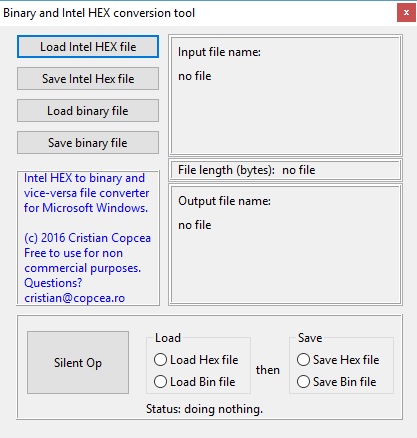
So I wrote my own version of a tool that converts from Intel HEX to binary and viceversa files up to 10Mbytes. The tool runs fine on Windows XP, Windows 7, Windows 8, Windows 8.1 and Windows 10.

It works in a very simple way: Load either Hex or binary files, save them as either Hex or binary. The “file length” caption shows the binary bytes, not the number of bytes actually on the file. Very useful to see if we went over the microcontroller flash or eeprom capacity.

Because a Intel HEX file may load not contiguous data and leave memory blocks not addressed, the application automatically fills all the memory block with 0xFF (not programmed memory location).

The hex editor works this way:

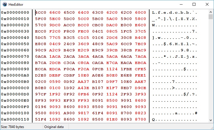
After loading a file, double click on the panel displaying the file name and a hex editor will appear:

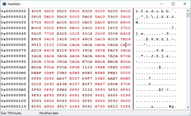
Data may be edited, deleted or inserted. Once data is modified, the status bar will indicate this, along with the new size of the data:


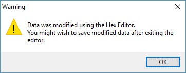
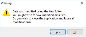
At this time, whenever the editor window or the main application is closed, warning dialogs will pop up, telling you that data is modified and that it should be saved.

Saving data in either format or loading a new file resets both the app and the editor, suppressing the warnings pop-ups until a new data edit is performed.

After using the editor to alter data, double clicking on the file name does not reload the file but shows the modified data into the editor instead.


In case one wishes to repeat the same conversion over and over during a project development, pressing the “Silent Op” button after having performed one conversion will redo that conversion silently, without popping the dialog windows for file names. Also, upon performing the first conversion manually, the tool remembers file names but also file types, and sets the radio buttons accordingly.

The “Silent Op” button does not do data manipulation. It just loads a file, converts it according to your choice and saves it.


This tool was written in Pascal and compiled with the free pascal IDE, Lazarus.

The hex editor is provided as-is by tkweb, here.

The tool is free for non commercial use.

Download here the Lazarus source files, including the hex editor package.

Download here the zipped Windows executable.


Jun 132015
 

Untitled

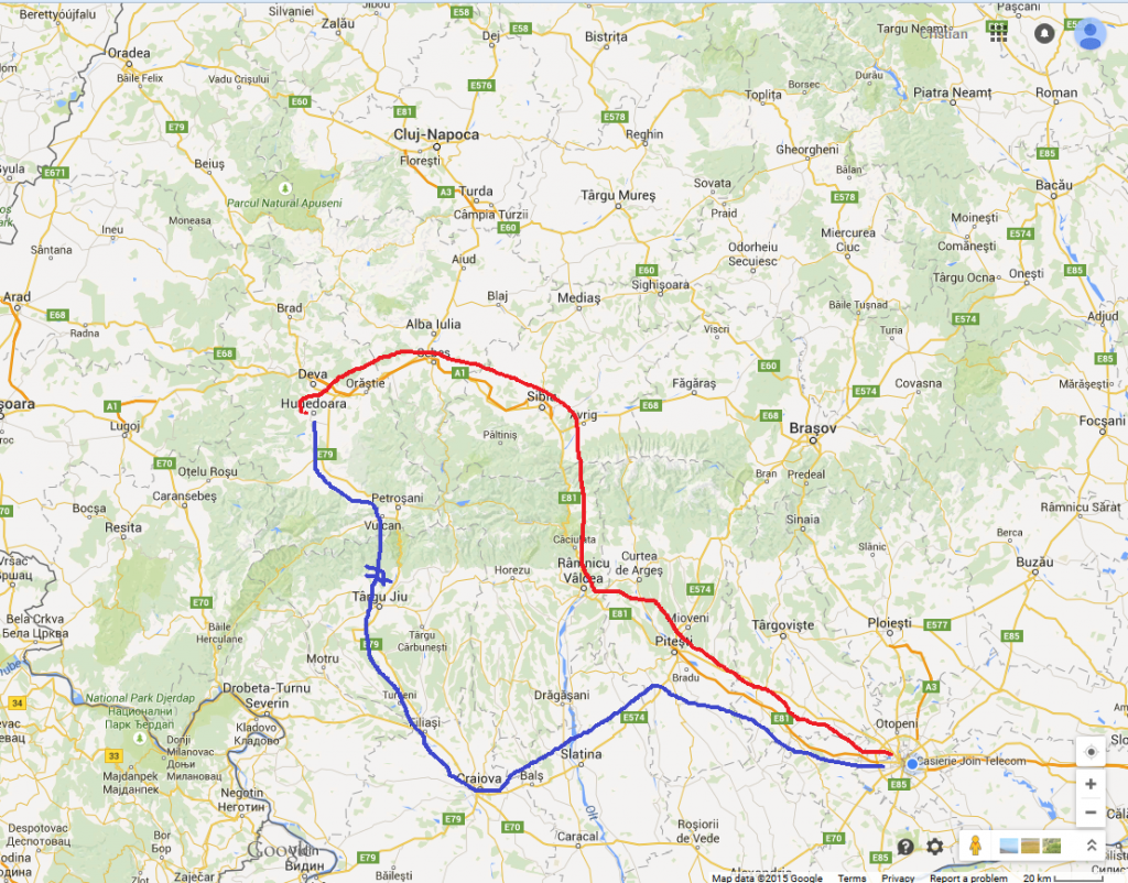
I rode on the red trail on my leave and then on the blue trail on my way back home. The two blue lines show the moment the recording stops, on the way back.

Almost 4 hours of raw footage. Long, I know, but also a way to show some of Romania’s beautiful landscapes, as I saw them from my motorcycle.

Enjoy.

Mar 122015
 

0. Foreword

Please, do not post elsewhere the code found here.

– The code should reside in one place and people should use links to my site instead. I have a hard time browsing the Internet for pieces of code sometimes, and finding old or obsolete code instead of links to the original developer is always a pain in the ass.

– I expect people to comment on the code and make optimizations/new developments, especially for student usage. Having this in mind, the code itself is an ongoing process which can be followed by students, from its first state (intelligible, but unoptimized) to its latest state (optimized, but unintelligible). Many people asked me how the code becomes awful and almost impossible to understand. It is my chance to show that I always start from a human approach and I am ending to a computer approach, and that this is always an endeavour that takes time and patience and endless computations and verifications, it doesn’t just come from thin air.

– the last reason is that I collect stats on page visits and downloads, which show me where to insist with open source development and where not to. I cannot collect stats from foreign sites, nor do I wish or have the time to do so.

Thank you!

1. Introduction

I have bought 3 pieces of SKU14220 – DIY 4 Digit LED Electronic Clock Kit Large Screen Red Blue Green LED from banggood.  At ~ US$12, it seemed a good deal and most interesting. Following my experience with the EC1204B clock, I was almost sure the firmware was going to be bad.

Bad is a nice thing to say. The firmware was horrible:

– it doesn’t show day/month/year;

– the setup is tricky and not easy to remember/understand;

– it lacks temperature;

– many people comment it is too bright during the night.

– the STC 15F204EA processor was a bad choice. 4K of flash do not suffice to build a nice and comfortable firmware for the end user, in my experience this design needs an processor with at least 8k flash.

So I decided to modify the latest firmware for the EC1204B clock and make it available for this version, with the necessary modifications.


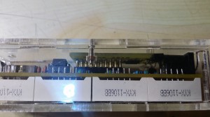
Figure 1 – SKU142210 clock assembled – bottom view

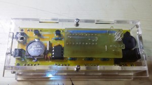
Figure 2 – SKU142210 clock assembled – top view

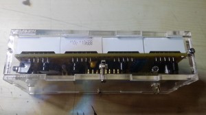
Figure 3 – SKU142210 clock assembled – rear view

Disclaimer:

The software/firmware presented here is a complete rewrite from scratch, just by observing the schematic and by understanding the way it works. It did not involve any kind of disassembly of the original firmware, reverse engineering or other similar stuff.

I do not condone copying the work of others in any way. However, progress is difficult to achieve these days from zero and it is easier to build up on something that already exists, while respecting the original work and effort.

I advice my readers to buy Banggood kits, the PCB has an excellent quality and all the parts delivered will be used, even with the modifications I suggest in this post. The idea is to start learning soldering and coding using affordable ressources.


 2. Hardware modifications


Video 1: The modified clock

After studying the schematic, it became obvious the only thing that needed to be replaced was the processor itself, with another firmware.

I couldn’t find any Atmel processor compatible pin to pin with the original, STC 15F204EA processor. The available place to insert a custom PCB in the processor’s slot is also narrow, so space would be of the essence in choosing a replacement processor.

This is why I have decided to use an ATmega8 AU, which is the smd version of the ATmega8.

Supplementary, a DS18B20 was added to measure temperature along with a photo-transistor, to implement automatic dimming of the display.


From a mechanical point of view, the programming pins were designed to go through the plexiglass wall, in order to allow programming of the device even when it is fully enclosed, without the need to disassemble the enclosure (see Figure 3 above).

2.1 Schematic

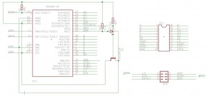
schematic


 2.2 PCB

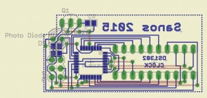
PCB

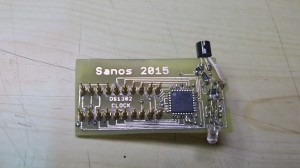
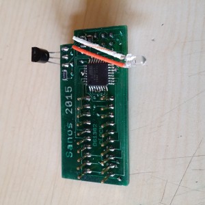
 2.3 The actual PCB

20150419_101648

Figure 5. The bottom side of the PCB

Figure 6. The top side of the PCB

 3 Software-firmware


The software, or firmware, is a variation of the software used for the EC1204B clock, in a previous post of mine.

Disregarding the process of eliminating pieces of code that did not apply to this particular clock, the two main additions are:

-the implementation of analog reading from a photo-diode, quite straightforward process;

– the implementation of digital dimming a multiplexed display.

A few words about the latter. The problem was to dim the display without having disturbing light shifts.

How it was done: In a multiplexed display, only one digit is lit a a time, with the specific data for that digit. Then, we go to the second digit and so on until the last. Basically we have an eternal cycle of lighting each digit at a time, cycle equal to the number of digits to be lit. What if we would add to this cycle “dead” times, when we don’t lit any digit? The result will be a software pwm on the multiplexed digits, up to the point when all the digits start to tremble. After a few trials, I have discovered that this has to stop at around 50 cycles. After 50 cycles, the dimming process isn’t perceived by the human eye, but it inserts this trembling of the digits.

The relationship between the level of light and the dimming is a simple transformation of the first degree, where dimming is inversely proportional to the level of light. The actual parameters are decided by experimenting. In this particular case, I had:

0 light -> 50 dimming cycles

50 light -> 4 dimming cycles.

The transformation became : cycles = (54-light), which is a rough approximation of the hypothesis above. A supplementary condition is also in effect, after reading the light value:

if (light>50) light=50;

This was necessary from direct observation: at 50 light, the display was too dimmed and the light  value (0-100) didn’t correspond well with the dimming if it was to be used full scale.


Feel free to play with the code and try to modify and optimize it. I hope it is easy enough to understand after 1-2 hours of study, in its most intimate details.

 4. How it works

The upper button is the “set” button. The lower button is the “select” button.


  • Pressing the Set button will cycle between the DS18B20 temperature sensors present at start up. On the board there is only one sensor, but you may solder several other sensors, all connected in parallel, and the device detects them at start up.
  • Pressing the Select button will enable you to program the microcontroller:
    • A short press (less than 5s) will show the date and month. Pressing it again will show the year. One more press reverts to clock display.
    • A longer press (6-10s) will enter the alarm set mode. Press set to cycle between alarm hour, minutes, alarm enable and memory storage. Press select at each stage to cycle possible values (0-23 for hours, 0-59 for minutes, on/off for enable);
    • A longer press (11-15s) will enter the clock set mode. Press set to cycle between year, month, day, minutes, hours and memory storage. Press select at each stage to cycle possible values;
    • A longer press (16-20s) will enter display mode. Press set to cycle between on, off and memory storage. Press select at each stage to cycle possible values;
    • A longer press (21-25s) will enter the temperature unit select mode. Press set to cycle between C,F and memory storage. Press select at each stage to cycle possible values;

At each stage, the last select key press is the memory storage. After storing selected parameters, the clock will beep. If you fail to store parameters (i.e. you do not press the button), the parameters will be in effect until the next reset of the clock.

5. Download

All the project for Atmel Studio 4, including a PDF with the PCB printout and necessary datasheets for parts (DS1302, DS18B20) can be downloaded here.

Following Bob Pike’s request to have the firmware show temperatures in F instead of C, the code was modified with the possibility to program the temperature display unit. The latest version can be downloaded here.

Last edit: 18.04.2015

6. Semi-automatic software drift compensation

Many people (including me) complain about the DS1302 drift, related to badly manufactured quartz resonators that do not offer a real 32 kHz (32768 Hz) clock.

The drift may become so big, a clock can have easily +- 10 minutes drift in a matter of months. Having two or more clocks in different rooms may easily lead to headaches in the morning when the decision to leave for work becomes a growing pain week after week.

The best practice would be to insert a trimmer capacitor in series with the quartz and set it to obtain a 32768 Hz clock. Even this practice is prone to errors due to:

– bringing a metallic screwdriver next to the trimmer alters its capacity. After setting the trimmer it would change its capacity again, hence the clock;

– normal trimmers are influenced by temperature. Just a little, but enough to generate a 1-minute drift every month or so;

– usually there is no or very little space on the PCB to insert a trimmer properly;

– the DS1302 clock could stop if a trimmer inserted in the circuit.

I have imagined a software solution to the drift, by calculating it in between two clock settings.

I began by asking myself what would be a disturbing drift, and I came with 5 minutes per year at a minimum, as being disturbing. However, setting the clock every year wouldn’t be too much to do, since I already set the clock twice a year when the daylight saving time appears and disappears.

5 minutes per year would mean a drift of roughly 5*60/12=25 seconds a month, less than 1 second per day.

Since the setting is done manually and one could press the set button with a 1 second drift, if the setting would be done after 20 days, it would lead to a supplementary error drift of 365/20=18.25 seconds a year, which is less than a minute per year: it wouldn’t even be noticeable.

The whole idea is to set the clock twice in the same month from a good time source (like your PC, after synchronizing its time with a time server). Why during the same month? Just to make the subroutine that computes time difference easier and less flash consuming. Anyway, there’s less than 1K of flash available for this with this project.

So: you set the clock on the 1st of the month and then you set it again on the 20th or 30th of the month.

The software computes the time difference from the two settings, which were made using a good time source and it will also compute the time difference the DS1302 has run, thus determining the time drift in a given period of time (let’s say 34 seconds in 28 days).

28 days equal 28*24*60=40320 seconds

So we have a drift of 34 seconds every 40320 seconds, which means a drift of 1 second every 1185(.88) seconds.

The clock will remember this drift and the processor will either add or subtract (depending on whether the drift is positive or negative) one second every 1185 seconds, by reading and rewriting the seconds in the DS1302.

Two errors are now in place:

– a 0.88 second (from rounding 1185.88 to 1185) every 40320 seconds, leading to roughly 12 seconds a year: almost non existent;

– a supplementary error drift from manipulation of the setting button of 365/20=18.25 seconds a year: almost non existent either;

In fact, this kind of semi-automatic drift compensation can lead to an error of at most 30 seconds a year, much lower than we could obtain by inserting a trimmer and setting it to achieve a 32kHz clock for the DS1302. We would experience annoying drifts in 10 years of non-stop operation of the clock.

What if we set the clock in different months? The software compares the month and the year of the last setting and the previous one. If these do not match, the clock drift is set to zero and there is no automatic drift compensation. A new clock setting in the same month would trigger a new drift computation and automatic drift compensation.

What if we set the time more than once during the same month? The software would take into consideration the last interval between two settings. If the interval is too low (e.g. 3 days) it could lead to a wrong computation of the drift compensation.

In order to set the drift compensation to zero, please operate two consecutive settings one after the other or by changing the month or year.

This version of the firmware can be downloaded here.

7.  Bug fixes, additions and optimizations

While working on my other project, the EC1204B Led rotating clock and implementing some requests from my readers, I have discovered ways to improve the code and also minor bugs that were addressed.

  • the code to multiplex the data on the display was optimized;
  • there was a bug while displaying temperatures over 100. It was fixed.
  • the colon display was modified. Now the colon displays whenever a second starts instead of displaying it on odd seconds only.
  • Peter Casper had a request to alternatively show the clock and the temperature, for he wishes to use the clock in an infrared-heated room.I thought using the same idea as above, so a new EEMEM variable was defined and if at programming time it is equal to 1, it fires a condition in the main loop that shows the temperature for 1 second every 10 seconds. It displays just with one (or the first) temperature sensor.Some optimizations to the display routine were also made.Because this firmware is about to hit the available flash memory in the mega8515, I had to look closely of the size of the binary data that was about to be burned into the MCU. How to do this, since the HEX file size has nothing to do with the size of the binary code? I have written this morning a Windows tool that converts Intel HEX files to binary and viceversa + it allows for automation…well, silent repetition of a load and save operations. I know, I am lazy, that’s why I wished for automation. Find what it is all about in this post.This version of the firmware can be downloaded here.

8. Combining all latest developments in one and allowing for setup without the need to reprogram the flash

While working on the latest requests for US mode (12H display and Fahnrenheit instead of Celsius), I used EEPROM variables to shorten the code and allow for its implementation. Unfortunately, to change these modes, the clock needed to be reprogrammed.

After many optimizations, I have succeeded to implement a way to set these modes without the need for a programmer.

Toggle between US and EU mode is now done from the menu itself:

  • EU mode displays 24H and Celsius. Setting the clock and alarm shows 24H.
  • US mode displays 12H and Fahnrenheit. Setting the clock and alarm shows 12H with A or P indicator for AM/PM.

Resetting the clock while pressing the SET key will toggle between regular clock display and clock/temperature display (temperature is displayes for 1 second every 10 seconds).

Enjoy downloading the latest firmware, datasheets etc, here.

At this moment, the firmware has 8160 bytes, further development on this firware being almost impossible, at least with the ATmega8.

9. It becomes a never ending story, huh?

Following the latest developments on the EC1204B clock, a new set of improvements to the code were added:

  • the code was optimized, again, to lower its size;
  • the ghost digit disappeared;
  • the clock can measure now negative temperatures on both C and F;
  • toggling between EU and US modes may also be done by keeping SET pressed at startup. It can also be changed from the menu.

Enjoy downloading the latest firmware, datasheets etc, here.


Last edited 17/01/2017

Dec 152014
 

Timer for horticulture

I love growing plants. Besides loving plants, I see this as a challenge to do…more.

Like growing coconut trees from seed, peppers. Usually I start planting them during winter, so the plant will be already grown during its first summertime.

Growing oriental and tropical plants during harsh winters in Romania is quite a challenge. Plants need warmth, which is available, but they also need light. Lots of light, which in turn is not available indoors without extra lighting.

A few years ago I started looking into this matter and I came up with a solution which solves the matter of having strong plants that will not die during winter from the lack of light.


1. The light itself.

A plant looks green because green is the color it reflects from the whole light spectrum. The plant doesn’t need green light, it needs instead almost all colors, from infrared to ultraviolet, to make photosynthesis and generate nutrients.

I have conceived a small Led lighting plate, made from half of an A4 board.

Schematic:

The Leds are all 5050, with 3 leds on each chip.

PCB:

The PCB should be populated like this:


WW=Ward White

CW=Cold White

R=Red

O=Orange

B=Blue

UV=Ultra Violet

All the leds are easily found on Ebay, quite cheap.


Next, a timer would come in handy in order to automate the lighting process.


Schematic:

1. – Power stage

2. – Micro-controller stage

3. – Keyboard and ISP stage

4. – Power Mosfet stage

5. – Display stage

6. – PCB

As in my other timers designs, the core is an Atmel micro-controller, in this particular case an ATMega8, because I needed an analog input to measure the light intensity and more flash, both unavailable on the small AtTiny2313.


How it works:

When started, the device shows the light intensity (0-100) and it starts assessing the conditions to start or stop the timer.  After a few seconds, in goes into power saving mode, lighting just the 3rd decimal point every second. The power saving mode is necessary to let the 7805 cool down because of the direct drive of the 7-segments display.

Every 15 seconds, it display for 2 seconds:

– the light intensity, on the form L.XXX;

– the threshold that was set up, on the form P.XXX;

– the remaining time of lighting (the current value of the timer), in the form HH.MM.

Yes, this timer does not show seconds anymore, it shows hours and minutes.

The left and right keys are increasing and decreasing respectively the time set for the timer or the threshold.

The GO key circles between the current light intensity (0-100, where 0 is dark and 100 is fully lit), the threshold and the time to set for the timer.

LEFT and RIGHT keys pressed simultaneously will write in EEPROM both the timer countdown value and the threshold value. set up by the user. At the next power-up, these will be the values used by default for countdown and threshold. After writing these values in EEPROM, the device shows “8888” for 2 seconds.

Any key press resets the timer and shuts it down, if in operation.

Left alone, the device performs the following:

– When the sun sets and the light goes beyond the set threshold, it waits for one minute and starts the timer. The timer will count backwards, keeping the lighting plate lit for the specified hours and minutes.

– When the timer expires, the light shuts off. The timer is programmable between 0 and 12 hours, with 10 minutes increments. The timer will not start again without the condition of the rising sun: the light must go over the threshold for 10 minutes, to reset the device and allow it to begin a new cycle. The 10 minutes are necessary in order not to reset the device if, for example, one is lighting the room for a period less than 10 minutes.

– During countdown, the timer can be shut off by pressing any key. This will also make the device reset and begin lighting again if the light goes beyond the specified threshold.


The code is written in C and compiles under AVR Studio 4.

The fuses for AtMega8 are set as follows:


RSTDISBL   - disabled 
WDTON      - disabled 
SPIEN      - enabled 
EESAVE     - disabled
BOOTSZ     - Boot flash size=128 words
BOOTRST    - disabled
CKOPT      - disabled
BODLEVEL   - brown-out detection at VCC=2.7V
BODEN      - enabled
SUT_CKSEL  - Internal RC Oscillator 8MHz; Start-up time: 14CK + 65 ms


AVR Studio 4 C code:

#include <stdlib.h>
#include <avr/io.h>
#include <avr/interrupt.h>
#include <avr/eeprom.h>
#include <avr/sleep.h>
#include <util/delay.h>
#include "config.h"
#include "adc.h"


uint16_t EEMEM Etime=240;    //240 default
uint16_t Def_time=240;
uint8_t Programmedtime=240;
uint8_t EEMEM EThreshold=50;
uint8_t Def_Threshold=50;

//global variables for isr()
uint16_t time, digit, decimal;
uint8_t wdisplay=0;
uint8_t t;
uint8_t LedOn=0;
//uint8_t ThresholdSetup=0;
uint8_t UVValue=100;
uint8_t Threshold=0;
uint8_t light,cancount,counted, counting;

//keys definition
#define GO        5
#define RIGHT     3
#define LEFT     4
#define KPIN  PINB
uint8_t keypressed=1;        //a key was pressed
uint16_t t1=0,t2=0,t3=0,t4=0,t5=0;
uint8_t Powersave=0;

#define SEG_a 0x02
#define SEG_b 0x01
#define SEG_c 0x10
#define SEG_d 0x40
#define SEG_e 0x20
#define SEG_f 0x04
#define SEG_g 0x08
#define SEG_dot 0x80


#define MuxPort PORTB
#define MuxDigit0 DDB0
#define MuxDigit1 DDB1
#define MuxDigit2 DDB6
#define MuxDigit3 DDB7
#define DataPort PORTD


uint16_t digit_addressed=0;
uint8_t d[8];
uint16_t pulseinterval;
uint16_t maxpulseinterval=512;
uint8_t pulsing=0;


//character definition
//a<->f and b<->g are inverted software.

unsigned char seg[]=
{
    //negative logic
    (SEG_g|SEG_dot),                                         // 0
    (SEG_a|SEG_d|SEG_e|SEG_f|SEG_g|SEG_dot),                // 1
    (SEG_c|SEG_f|SEG_dot),                                     // 2
    (SEG_e|SEG_f|SEG_dot),                                     // 3
    (SEG_a|SEG_d|SEG_e|SEG_dot),                             // 4
    (SEG_b|SEG_e)|SEG_dot,                                     // 5
    (SEG_b|SEG_dot),                                         // 6
    (SEG_d|SEG_e|SEG_f|SEG_g|SEG_dot),                        // 7
    (SEG_dot),                                                 // 8
    (SEG_e|SEG_dot),                                         // 9
    (SEG_a|SEG_b|SEG_c|SEG_d|SEG_e|SEG_f|SEG_g),             // NULL DISPLAY FOR POWER SAVE WITHOUT DOT
    (SEG_a|SEG_b|SEG_c|SEG_g),                                // L
    (SEG_c|SEG_d),                                             // P
    (SEG_a|SEG_b|SEG_c|SEG_d|SEG_e|SEG_f|SEG_g|SEG_dot)     // NULL DISPLAY FOR POWER SAVE WITH DOT
};

void init(void)
{
//timer 0 setup
    TCNT0 = 0x00 ;
    TCCR0 = 0x03; //prescaler of 64 0x03
    TIMSK = 0x01; //overflow irq req'd
//timer1 setup
    //we need PB4 (OC1B) as PWM but PB3 (PC1A) as standard output port
    TCCR1A = 
    0 << COM1A1 | /* normal port operation, PWM disabled */
    0 << COM1A0 |
    1 << COM1B1 | /* not inverted */
    0 << COM1B0 |
    1 << WGM10  | /* fast pwm 8 bit*/
    0 << WGM11  ; /* fast pwm 8 bit*/

    TCCR1B = 
    1 << WGM12 |
    0 << WGM13 | /*fast pwm non inverting max FF*/
    1 << CS10  | /* prescaler /8 = 250 Hz PWM */
    1 << CS11  |
    0 << CS12  ;

    ADCSRA |= _BV( ADEN ) | _BV(ADPS0) | _BV(ADPS1) | _BV(ADPS2);
//    GIMSK = 0b00100000;    // turns on pin change interrupts
//    PCMSK = 0b11100000;    // turn on interrupts on pins PB0, PB1, 
    sei();
    DDRC  =0x00;                                    //PORTC defined as input
    PORTC=0x01;                                        //pull resistors up on port C
    DDRB  =_BV(0)|_BV(1)|_BV(2)|_BV(6)|_BV(7);        //bits 0-2 and 6-7 of PORTB are defined as outputs
    PORTB =_BV(0)|_BV(1)|_BV(2)|_BV(6)|_BV(7);        //bits 3-5 of PORTB are defined as inputs
    DDRB  = DDRB& ~_BV(2);                            //set PB2 as input, to clear residual PWM

    PORTD=0xff;
    DDRD =0xff;
    pulsing=0;                //pulsing
    pulseinterval=0;
    time= eeprom_read_word(&Etime);
    if (time==0xFFFF)        //not  EEPROM
    {
        time=Def_time;
        eeprom_write_word(&Etime, Def_time);
    }

    Threshold= eeprom_read_byte(&EThreshold);
    if (Threshold==0xFF)        //not programmed EEPROM
    {
        Threshold=Def_Threshold;
        eeprom_write_byte(&EThreshold, Def_Threshold);
    }
    OCR1B=light*255/100;                                    //init value on PWM at zero

}


//interrupt routine for character display
ISR(TIMER0_OVF_vect)
{
    pulseinterval++;
    if (pulseinterval>maxpulseinterval) pulseinterval=0;
    if ((pulsing==1) && (pulseinterval > maxpulseinterval/2))
    {
        MuxPort=(1<<DDB0) | (1<<DDB1)| (1<<DDB6)| (1<<DDB7);
    }
    else
    {    
        PORTD = ~(d[digit_addressed]);

        switch (digit_addressed)
        {
            case 0: 
            {
                MuxPort=(0<<MuxDigit0) | (1<<MuxDigit1)| (1<<MuxDigit2)| (1<<MuxDigit3); 
            break;
            }     
            case 1: 
            {
                MuxPort=(1<<MuxDigit0) | (0<<MuxDigit1)| (1<<MuxDigit2)| (1<<MuxDigit3); 
                if ((wdisplay==2) && (Powersave!=1))
                {
                    PORTD|=_BV(7);
                }         
                else
                {
                PORTD=PORTD&~_BV(7);
                }//set   bit 7 port d (dot point) if we display time
            break;
            }
            case 2: 
            {
                MuxPort=(1<<MuxDigit0) | (1<<MuxDigit1)| (1<<MuxDigit2)| (0<<MuxDigit3); 
            break;
            }    
            default:
            {
                MuxPort=(1<<MuxDigit0) | (1<<MuxDigit1)| (0<<MuxDigit2)| (1<<MuxDigit3); 
            }    
        }
        digit_addressed++;
        if(digit_addressed>=4) digit_addressed=0;
    }
}


void display(void)
{
    uint8_t hr, min;
    if (Powersave!=1)
    {
        if (wdisplay==0)    //light level
        {
            if (digit==100)
            {
                d[4]=seg[11];
                d[5]=1;
                d[6]=0;
                d[7]=0;
            }
            else    
            {
                d[4]=seg[11];
                d[5]=0;
                d[6]=digit/10;
                d[7]=digit- d[6]*10;
            }
            d[0]=seg[11];
            if (digit==100) d[1]= seg[1];    else d[1]=seg[13];
            if (digit>=10)  d[2]= seg[d[6]]; else d[2]=seg[13];
            d[3]= seg[d[7]];
        }
        else
        if (wdisplay==1)    //threshold
        {
            if (digit==100)
            {
                d[4]=seg[12];
                d[5]=1;
                d[6]=0;
                d[7]=0;
            }
            else    
            {
                d[4]=seg[12];
                d[5]=0;
                d[6]=digit/10;
                d[7]=digit- d[6]*10;
            }
            d[0]=seg[12];
            if (digit==100) d[1]= seg[1];    else d[1]=seg[13];
            if (digit>=10)  d[2]= seg[d[6]]; else d[2]=seg[13];
            d[3]= seg[d[7]];
        }
        else
        if (wdisplay==2)    //time
        {
            hr=digit/60;
            min=digit-hr*60;
        
            //computing digits
            d[4]=hr/10;
            d[5]=hr-d[4]*10;
            d[6]=min/10;
            d[7]=min-d[6]*10;
            d[0]= seg[d[4]];
            d[1]= seg[d[5]];
            d[2]= seg[d[6]];
            d[3]= seg[d[7]];
        }
    }
    else
    {
        d[4]=counting;
        d[5]=counted;
        d[6]=cancount;
        d[0]=seg[d[4]];
        d[1]=seg[d[5]];
        d[2]=seg[d[6]];
        d[0]= seg[13];    //comment here for debugging
        d[1]= seg[13];  //comment here for debugging
        d[2]= seg[10];  //comment here for debugging
        d[3]= seg[13];
    }
}


void readkeysT1(void)
{
//LEFT AND RIGHT keys

//LEFT key
    if (bit_is_clear(KPIN, LEFT) && bit_is_clear(KPIN, RIGHT))
    {
        eeprom_write_word(&Etime, time);
        eeprom_write_byte(&EThreshold, Threshold);
        keypressed=1;
        d[0]= seg[8];
        d[1]= seg[8];
        d[2]= seg[8];
        d[3]= seg[8];
        _delay_ms(2000);
    }
    else
    if bit_is_clear(KPIN, LEFT) 
    {
        pulsing=0;
        counting=0;        //we're not counting
        counted=0;        //never did
        cancount=0;    //cannot count yet
        keypressed=1;
        _delay_ms(50);
        if (wdisplay==0) wdisplay=1;
        if (wdisplay==2)
        {
            time-=10;
            if (time>5999) time=0;
        }
        else
        {
            Threshold--;
            if (Threshold==0xFF) Threshold=0;
        }
    }
    else
//RIGHT key
    if bit_is_clear(KPIN, RIGHT) 
    {
        pulsing=0;
        counting=0;        //we're not counting
        counted=0;        //never did
        cancount=0;    //cannot count yet
        keypressed=1;
        _delay_ms(50);
        if (wdisplay==0) wdisplay=1;
        if (wdisplay==2)
        {
            time+=10;
            if (time>720) time=720;
        }
        else
        {
            Threshold++;
            if (Threshold>100) Threshold=100;
        }
    }
    else
        if bit_is_clear(KPIN, GO) 
    {
        pulsing=0;
        keypressed=1;
        Powersave=0;
        wdisplay++;
        counting=0;        //we're not counting
        counted=0;        //never did
        cancount=0;    //cannot count yet
        if (wdisplay==3) wdisplay=0;
        _delay_ms(100);
        loop_until_bit_is_set(KPIN,GO);
    }
    else    keypressed=0;
}


void testfordisplaysleep(void)
{
    if (keypressed==0)    //if there is no key pressed
    {
        t1++;            
        if (t1==100)    //wait ~10 seconds
        {
            t1=0;        
            Powersave=1;//and put display to sleep
            pulsing=1;
        }
    }
    else                //on any key press 
    {    
        t1=0;
        t2=0;
        Powersave=0;    //wake up display

    }
    if ((t2>0) || (Powersave==1))    //display values during powersave
    {
        t2++;
        if ((t2>200) && (t2<235))
        {
            Powersave=0;
            wdisplay=0;
            pulsing=0;
        }
        else
        if ((t2>240) && (t2<275))
        {
            Powersave=0;
            wdisplay=1;
            pulsing=0;
        }
        else
        if ((t2>280) && (t2<315))
        {
            Powersave=0;
            wdisplay=2;
            pulsing=0;
        }
        else
        if (t2>315)
        {
            Powersave=1;
            t2=0;
            pulsing=1;
        }
        else
        {
            Powersave=1;
            pulsing=1;
        }
    }
}

void ShowLight()
{

/*
Trebuie evitate aprinderile accidentale de lumina, astfel:


Daca lumina scade sub prag timp de 1 minut, aprindem lumina artificiala si incepem numaratoarea inversa
La sfarsitul numaratorii inverse, inchidem lumina pana se ridica iar nivelul de lumina peste prag, timp de 1 minut.

Daca, in timpul numaratorii inverse, apare lumina peste prag, numaram mai departe.fara sa ne intereseze aspectul

*/
        if (counted==0)                            //if there was no count during the day
        {
            if (light<Threshold)                //if light goes under the threshold
            {
                if (counting==0)
                {
                    t3++;                            //start counting one minute
                    if (t3==800)                    //if one minute passes, i.e. 800 cycles
                    {
                        cancount=1;                    //we then can count
                        t3=0;                        //we reset the 1 minute delay
                        Programmedtime=time;        //setting count back to the set value
                    }
                }
            }
            else                                //still waiting for 1 minute to pass
            {
                if (counting==0)                //if light goes over the threshold for 10 minutes (new daylight) and we're not counting
                {
                    t5++;                                //start counting 10 minutes
                    if (t5==8000)                        //if 10 minutes pass, i.e. 8000 cycles
                    {
                        counted=0;                        //we reset everything
                        cancount=0;
                        counting=0;
                        t5=0;                            //including the 10 minutes delay
                        t3=0;
                    }
                }
            }
        }
        else                                        //if there was a count during the day
        {                                            //we have to reset the count on the next day
            if (light>Threshold)                     //if light goes over the threshold for 10 minutes (new daylight)
            {
                t5++;                                //start counting one minute
                if (t5==8000)                        //if 10 minutes pass, i.e. 8000 cycles
                {
                    counted=0;                        //we reset everything
                    cancount=0;
                    counting=0;
                    t5=0;                            //including the 10 minutes delay
                }
            }

        }


}


void count()
{

            if (cancount==0)             //if we can't count because we have either counted or because the light didn't diminish under the threshold
            {
                counting=0;                //not counting
                DDRB  = DDRB& ~_BV(2);    //turn off the lights
            }
            else                        //if we can count
            {
                counting=1;                //we're counting
                t4++;
                if (t4==800)            //if 1 minute passes (800 cycles)
                {
                    Programmedtime--;    //we then can count backwards
                    t4=0;                //we reset the 1 minute delay
                }
                if (Programmedtime==0)    //if counting ends
                {
                    cancount=0;            //can't count anymore
                    counted=1;            //we have just finished counting
                    counting=0;            //not counting anymore
                    Programmedtime=time;//reset counter
                }
                DDRB |=_BV(2);            //turn on the lighta
//                OCR1B=(100-light)*255/100; //de calculat iluminarea cu 105 sub prag si 100% la intuneric
                OCR1B=255;                
            }
}

int main()
 
{
    init();
    _delay_ms(10);
    LedOn=0;
    PORTD=_BV(7);    // keep DP lit
    t1=0;
    keypressed=1;
    counting=0;        //we're not counting
    counted=0;        //never did
    cancount=0;    //cannot count yet

    while(1)
    {
        readkeysT1();                            //read key
        display();                                //display number
        _delay_ms(50);                            //wait a little bit
        testfordisplaysleep();                    //put the display to sleep if needed
        if (wdisplay==0) digit=light;            //display whatever values are needed
        else
        if (wdisplay==1) digit=Threshold;
        else
        if (wdisplay==2)
        {
            if (counting==0)     
                digit=time;
            else
            {
                digit=Programmedtime;
            }
        }
        light=GetLight();                        //read light level
        ShowLight();                            //lights on if needed
        count();
    }

}
 

The ADC header file:

#ifndef ADC_H_
#define ADC_H_

#include <stdint.h>

/**
 * \name ADC channels for analog inputs
 * @{
 */
#define LIGHT_PIN 0
///@}

uint8_t GetADC( uint8_t channel );
uint8_t GetLight();

#endif 


The ADC C file:


#include "adc.h"
#include <avr/io.h>
#include <util/delay.h>
#include <stdlib.h>


uint8_t GetADC( uint8_t channel )
{

    uint8_t i, lum[100], lumend,a;
    ADMUX = channel | _BV( REFS0 ) | _BV(ADLAR); //8bit + AVCC
    lumend=0;

    for (i=0;i<100;i++)
    {
    //start conversion.
        ADCSRA |= _BV(ADSC);

         //wait for the 1st result
        loop_until_bit_is_clear( ADCSRA, ADSC );
        lum[i]= ADCH; //left adjusted = 8 bit
        lumend=(lumend*(i+1)+lum[i])/(i+2);
    }

    a=102-lumend*25/58;
    if (a>200) a=0;
    if (a>100) a=100;
    return a;
}

uint8_t GetLight()
{
    return GetADC( LIGHT_PIN );
}


If this is useful for you, please donate. I need to buy parts, make time to study and pay for the hosting. Thanks!


Sep 232012
 

Recent am achizitionat pentru casa niste becuri cu 60 de LED-uri, marca LOHUIS.

Din 7 becuri, 4 s-au ars in prima zi iar doua becuri au rezistat cca 1 saptamana.

Un singur bec mai functiona dupa prima saptamana.

Din acest motiv, m-am enervat si am purces la investigarea cauzei – si, eventual repararea becurilor.


Cu un cutitas, am desprins cu grija cablajul LED-urilor de pe soclul de sticla, si am descoperit, montat pe spatele cablajului cu LED-uri, un driver de curent continuu pentru aceste LED-uri.


Schema electrica a driverului de curent continuu este urmatoarea:

Cablajul driverului pentru LED-uri este urmatorul (aproximativ):


Lista componente :

R1: 570k ohmi/0,125W, miniatura

R2: 100 ohmi, 0,5W

R3: 470k ohmi, 0,125W, miniatura

R4: 50 ohmi/0,5W

C1: 470nF/400V, poliester multistrat

C2: 10uF/400V, electrolitic

C3: 10nF/1kV miniatura, poliester

D1-D4: 1N4001

Cum functioneaza circuitul:

Se obtine o cadere de tensiune suficient de importanta prin condensatorul de 470nF/400V (poliester) si rezistenta de 100 ohmi.

Tensiunea rezultata este redresata cu cele 4 diode iar tensiunea continua astfel obtinuta este filtrata cu condensatorii de 100nF si 10uF/400V.

Inca o cadere mica de tensiune se obtine inaintea conectarii LED-urilor, cu rezistorul de 50 ohmi legat in serie cu LED-urile.

Condensatorul de filtrare de 10nF, in paralel cu cel de 10uF “taie” varful de tensiune care apare la punerea sub tensiune a circuitului.

Cele doua rezistente de 470k montate in paralel cu condensatorii au ca rol descarcarea acestora in momentul intreruperii alimentarii, altfel ar fi periculos de lucrat pe circuit dupa decuplarea de la retea.

Problema circuitului si rezolvare:

Initial am crezut ca s-a ars vreun LED, insa toate erau OK.

Problema este rezistenta R2, de 100 ohmi, care era arsa la TOATE becurile, fara a afecta alte rezistente, condensatori sau diode redresoare.

Ori producatorul este de slaba calitate, ori a fost un lot de rezistente foarte slab calitativ.

Am inlocuit aceste rezistente de 100 ohmi, arse, cu alte rezistente de 100 ohmi/0,5W si becurile au reinceput sa functioneze.

Pe parcurs, s-au mai ars inca doua rezistente de 100 ohmi, de productie romaneasca, pe care le-am inlocuit iar, prima cu o rezistenta de 150 ohmi romaneasca si cealalalta cu o rezistenta de 330 ohmi ruseasca (MLT).

Dupa efectuarea acestor modificari, becurile si-au reluat viata si functioneaza normal.


Pacat de productia celor de la Lohuis, care vine cu un pret acceptabil avand in vedere numarul de piese utilizat (22 lei pentru un bec cu 60 de LED-uri). Utilizatorul de rand va arunca becurile la gunoi dupa cateva zile, daca nu este capabil sa si le repare, iar OPC-ul va fi asaltat de plangeri. Totul din cauza unei rezistente prost alese in circuit si a incapacitatii producatorului de a efectua teste riguroase inaintea punerii in productie si la vanzare.

Solutia cu LED-uri este in schimb viabila, cele 4 becuri montate in tavan in locul spoturilor dand o lumina omni (nu spot, ca inainte) MULT mai puternica decat becurile anterioare de 25W/bucata, la un consum de peste 10 ori mai mic decat cel initial.

Oct 202011
 

Din experienta pe care am acumulat-o la Join Telecom in lucrul cu clientii, combinata cu studiile si literatura de specialitate, reiese faptul ca utilizatorii de Internet nu numai ca nu isi pun intrebarile corecte ci si obtin raspunsuri incorecte, in majoritatea cazurilor prin manipulari publicitare care initial le iau ochii, apoi banii, ca urmare a semnarii de contracte paguboase, uneori pe termen lung si fara posibilitatea de a rezilia.

Accesul la Internet, care ofera utilizatorului final de la entertainement pana la cultura, informare de orice natura, are inca o latura tehnica destul de pronuntata. Alegerile tehnice proaste pot influenta masiv experienta de lucru pe Internet a utilizatorului final. Lipsa experientei si, de multe ori a unei comparatii corecte, face ca multi utilizatori sa considere ca fiind excelente solutii care sunt in realitate de calitate mediocra.

Articolul de fata incearca sa educe utilizatorul final in scopul invatarii acestuia care sunt alegerile corecte si in ce context trebuie acestea efectuate.

1. Adrese IP

Adresa IP este acel numar care identifica in mod unic un calculator care este legat la Internet. Unicitatea adresei IP este necesara, la fel cum este necesara unicitatea unui numar de telefon. Daca doua persoane ar avea acelasi numar de telefon, cum le-am mai putea deosebi?

Tehnic, o adresa IP este un numar pe patru octeti, iar pentru simplificarea notatiei si pentru usurinta memorarii, cei patru octeti au fost separati cu puncte, astfel incat o adresa IP are forma A.B.C.D, unde A,B,C si D sunt numere cuprinse intre 0 si 255.

La origine, exista un singur model de adrese IP, toate fiind Publice (adica vizibile din Internet direct, de la oricare alta adresa IP). Datorita faptului ca numarul adreselor IP este limitat la putin peste 4 miliarde (256*256*256*256=4.294.967.296), odata cu explozia Internetului brusc acest numar a devenit insuficient pentru nevoile actuale. O persoana poate utiliza simultan peste 5-6 adrese IP: doua laptopuri, un desktop, un telefon mobil cu wifi, routerul wifi si un prieten in vizita.

Porturi

Toata lumea a auzit de porturi, putini sunt cei care stiu ce sunt si la ce servesc.

Legatura dintre doua calculatoare se efectueaza pe modelul introducerii unui stecher intr-o priza de curent(socket in engleza). Priza este dispozitivul care ofera energie (in cazul calculatoarelor, ofera informatie), iar stecherul este cel care culege informatia dorita.

Dat fiind ca orice calculator trebuie sa poata accesa simultan informatie variata de la mai multe surse, trebuie sa aiba mai multe stechere.

La fel un server care ofera informatie, trebuie sa poata oferi simultan informatii catre mai multi destinatari, cu alte cuvinte trebuie sa aiba mai multe prize.

Dat fiind ca modul de comunicare este bidirectional, un canal de comunicatii al unui calculator oarecare poate fi atat priza cat si stecher, in functie de directia in care circula informatia. Canalul de comunicare este acea legatura priza-stecher, in care atat priza cat si stecherul au cate un numar alocat, identic sau diferit.

Cineva a stabilit ca orice calculator poate avea maxim 65535 porturi, din care primele 1024 au fost rezervate pentru servicii standard, iar restul au fost lasate libere pentru utilizare la libera alegere.

Modul general de utilizare al porturilor

Calculatoarele end-user (client) sunt de regula consumatoare de informatie (fac download), pe cand serverele sunt donatoare de informatie (fac upload). In realitate, prin intermediul unui canal de comunicatie informatia circula bidirectional, insa este favorizata una din directii. Cand deschideti o pagina de internet, calculatorul dumneavoastra efectueaza o cerere catre server iar acesta raspunde cu continutul paginii cerute. Cererea este de dimensiuni mici, insa pagina poate fi de dimensiuni uriase. De aici si favorizarea circulatiei intr-un sens. In acest caz, la nivelul conexiunii dumneavoastra se considera ca faceti download (descarcati informatie) pe cand la nivelul sererului apare un upload (o transmitere de informatie).

La calculatoarele client, sistemul de operare, oricare ar fi el, in momentul initierii unei conexiuni, cauta un stecher (port de iesire) care este liber, si realizeaza o conexiune intre acest port si portul (priza) serverului. In momentul stabilirii unei noi conexiuni, de regula se utilizeaza portul imediat urmator celui utilizat anterior pentru a stabili o conexiune cu noul server, insa nu este o regula de baza. Conexiunile sunt memorate intr-o tabela in memorie, pentru a se identifica in mod unic canalele de comunicatie.

De regula, o conexiune are notatia A.B.C.D:P-X.Y.Z.T:R , unde A.B.C.D este adresa IP originatoare, P este portul originator, X.Y.Z.T  este adresa IP de destinatie iar R este portul destinatie.

O intrebare care se ridica in mod natural, este aceasta: cum poate fi accesata o aceeasi pagina web de doua ori simultan de pe acelasi calculator?

Simplu:

La prima conexiune sistemul de operare client aloca, sa zicem, portul 32005.

In tabela de conexiuni va aparea legatura: A.B.C.D:32005 – X.Y.Z.T:80

unde A.B.C.D este adresa IP client, X.Y.Z.T este adresa IP a serverului, portul 32005 este portul alocat dinamic de catre sistemul de operare client, iar portul 80 este portul utilizat in mod normal pentru vizualizarea unei pagini web (protocol http).

La a doua conexiune sistemul de operare client aloca, portul urmator, 32006.

In tabela de conexiuni va aparea legatura: A.B.C.D:32006 – X.Y.Z.T:80

Dupa cum se vede, cele doua legaturi sunt unice, iar sistemul de operare identifica canalele de comunicatie in mod unic.

Adrese IP Publice

Adresele IP au forma A.B.C.D, unde A,B,C si D sunt cifre cuprinse intre 0 si 255. Notatia este o simpla conventie, evident ar fi fost posibil sa se aleaga la inceput si alta forma, insa daca aceasta este in uz, trebuie sa traim cu ea si sa nu ne punem intrebari suplimentare.

Toate adresele de la 0.0.0.0 la 255.255.255.255 sunt adrese publice, cu exceptia celor private si a celor speciale (vezi mai jos).

Adrese IP Private

Cineva destept a introdus conceptul de adrese private in scopul maririi numarului de adresare posibil. Astfel, adresele de la 192.168.0.0 la 192.168.255.255, 10.0.0.0 la 10.255.255.255 si 172.16.0.0 la 172.31.255.255 au fost scoase din Internet si puse deoparte pentru uz privat (de unde si denumirea de adrese private).

Adresele private:

– nu pot exista in Internet, din moment ce au fost scoase din lista de adrese valide;

– au nevoie de un translator (router, gateway) pentru a putea accesa internetul;

– pot fi utilizate de catre oricine, fara aprobare prealabila, in constructia unei retele private.

Adresele private au nevoie de un translator care sa efectueze conexiuni in numele lor si de aceea calculatorul care joaca rol de translator necesita de regula o putere de calcul semnificativa, daca are de tradus (translatat) multe adrese IP private. Este acelasi sistem utilizat la telefonia clasica, cu numere de interior intr-o institutie. Centralistul sau centrala telefonica este punctul in care se strang toate apelurile din interior si sunt translatate catre exterior. Translatarea adreselor IP private este numita NAT (Network Address Translation).

Practic, daca notam:

A.B.C.D = adresa IP a clientului cu adresa privata;

X.Y.Z.T = adresa IP a serverului care trebuie accesat;

K.L.M.N = adresa IP a translatorului;

P = portul de iesire al clientului;

R1 = portul de iesire al translatorului inspre Internet;

R2 = portul de iesire al translatorului inspre reteaua locala, cea cu adrese private;

S = portul de intrare al serverului;

Clientul A.B.C.D:P face o cerere catre X.Y.Z.T:S

Translatorul observa cererea, o translateaza, adica genereaza la randul lui cererea:

K.L.M.N:R1 – X.Y.Z.T:S

Cand se intoarce raspunsul pe canalul X.Y.Z.T:S – K.L.M.N:R1, translatorul trimite raspunsul catre clientul cu adresa privata:

K.L.M.N:R2 – A.B.C.D:P

Astfel, legatura dintre client si server este realizata prin intermediul translatorului in mod unic, utilizand aceasi regula de memorare a tabelelor de conexiuni.

Adrese APIPA (Automatic Private IP Addressing)

Adresele 169.254.0.1 pana la 169.254.255.254 sunt de asemenea adrese private, cu o utilizare speciala, in cazul in care un client face o cerere de adresa IP dar nu exista nici un server care sa i-o aloce. In acest caz, clientul isi auto-aloca in mod aleator o adresa Ip din acest interval. Daca apare un conflict (adresa auto-generata este deja in uz), exista un mecanism care detecteaza acest conflict iar procesul de auto-generaer se reia pana la disparitia conflictului.

2. Modele de conexiuni Client

2.1 Conexiunea cu adrese IP Publice

Conexiunea cu adrese IP publice este cea mai avantajoasa, deoarece in circuitul conexiunii dintre client si server nu exista intermediari de tipul NAT, iar transmiterea informatiei de la client la server si inapoi se face de catre circuite comutate, extrem de rapide, care nu interpreteaza si nu modifica informatia transmisa.

2.1.1 Conexiunea cu adrese IP Publice fixe (rezervate)

In cazul in care clientului i se aloca intotdeauna aceasi adresa IP publica, clientul poate, in plus fata de a fi un simplu client, sa devina de asemenea un server: calculatorul poate fi accesat intotdeauna de pe Internet, de oriunde, avand certitudinea ca este vorba intotdeauna despre acelasi calculator si nu de catre altul.

2.1.2 Conexiunea cu adrese IP Publice variabile (nerezervate)

In anumite cazuri, de regula in momentul in care furnizorul de Internet nu dispune de suficiente adrese IP pe cati clienti are, se practica alocarea de adrese IP publice variabile (este cazul RDS, Astral, Romtelecom). In acest caz, detinatorul calculatorului client nu poate sti ce adresa IP i s-a alocat, sau daca aceasta s-a modificat intre timp, si astfel nu isi poate utiliza calculatorul pe post de server, pentru a oferi servicii sau pur si simplu pentru a-si accesa calculatorul din alta retea de Internet. Clientul, in acest caz, este redus la nivelul de consumator

2.1.2 Conexiunea cu adrese IP Private.

Este cazul UPC, Astral, Romtelecom, Vodafone, Orange, Cosmote.

In acest caz nu numai ca calculatorul client nu mai poate fi accesat din afara sub nici o forma, dar existenta unui NAT la nivel macro, care deserveste sute sau mii de clienti simultan, poate conduce, si chiar conduce in anumite situatii, la:

– intarzieri semnificative din cauza ca translatorul NAT nu are putere suficienta de calcul in acel moment (este supra-aglomerat de cereri);

– nu poate efectua tranzactiile deoarece tabelele de NAT sunt pline:

In exemplul de mai sus am aratat ca un translator NAT are nevoie sa utilizeze doua porturi pentru a satisface cu succes cererea unui singur client pe un port. Cum insa numarul lui propriu de porturi este limitat la 65535, inseamna ca, indiferent de cat de puternic ar fi, nu poate satisface mai mult de (65535-1024)/2=32255 cereri simultane. orice alte cereri suplimentare fata de aceasta cifra sunt pur si simplu ignorate, creand intarzieri, de regula masive, la client.

Luand, din practica, un numar mediu de 200 de conexiuni per calculator client, acestea necesita 400 de conexiuni la nivelul NAT, micsorand numarul de calculatoare pe care un NAT le poate deservi simultan la doar 164. In momentul scrierii acestui articol, calculatorul meu avea 1496 de conexiuni simultane cu diversi. In cazul in care as fi utilizat un NAT si toti clientii ar fi fost in acesi situatie cu calculatorul meu, acesta nu ar fi putut prelucra informatia de la mai mult de 65535/2/1496 = 21 de calculatoare!

In mod evident, tabelele NAT sunt dinamice iar informatia despre un anumit canal de legatura dispare odata cu expirarea timpului de viata al acestuia (TTL=Time To Live), lasand libera calea catre efectuarea altor conexiuni. Problema nu dispare insa in totalitate si nu putine sunt cazurile de aparitie a asa-numitului bottleneck – strangulare a legaturii.

3. Rutere si WiFi

In afara retelelor de cartier, care utilizeaza rutere cu adrese IP publice fixe pentru stabilirea legaturii dintre clientii lor si restul Internetului, aproape toti ceilalti ISP care se adreseaza segmentului rezidential utilizeaza rutarea cu NAT (cu adrese private) sau cu adrese publice variabile., din cauza resurselor limitate de adrese IP pe care le au la dispozitie

Ruterele wifi montate la clienti preiau adresa publica sau privata alocata clientului si o retranslateaza catre mai multe adrese private. Aceste aparate au procesoare de mica sau medie putere, utilizate la translatarea cererilor clientului, conducand in final la:

– posibile pierderi de conexiuni;

– intarzieri in realizarea conexiunilor din cauza NAT si/sau a partii radio;

– imposibilitatea realizarii de conexiuni peer-to-peer (sau adresa publica la adresa publica – legaturi directe intre calculatoare din Internet);

Ruterele Wifi sunt si cele care cauzeaza cele mai multe probleme in retele, multe fiind de provenienta dubioasa sau prost construite. Am intalnit un numar foarte mare de cazuri in care disparitia alimentarii cu energie electrica pentru o perioada scurta, de 1-2 secunde, au condus la resetarea informatiilor din router iar acesta a trebuit reconfigurat, proces care nu este la indemana unui necunoscator.

Switch to mobile version
Advertisment ad adsense adlogger