So I buy a pair of these U5 Motorcycle LED Headlight Waterproof High Power Spot Light from the Internet, to mount it on my motorbike.
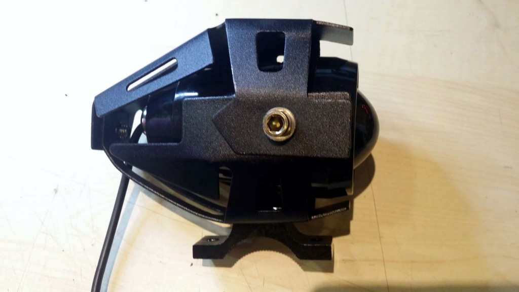
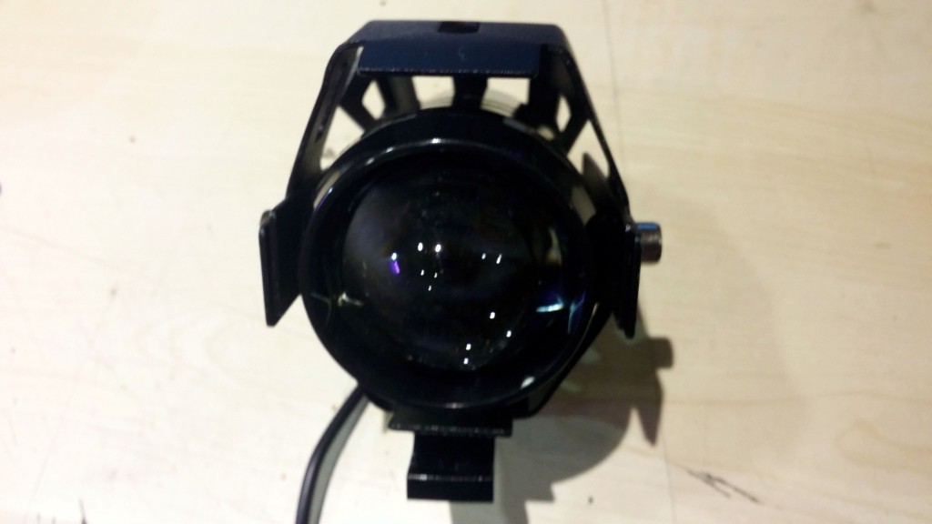
Nice finish, light…hmmm…bright but not VERY, so i decide to take a look at the specs, again.
Input Voltage:12V-80V DC
Actual power: 10W
Light Power: 15W
Flux: 3000LM
Range:200 meters
LED Color Temperature:6000k-7000k
Environment Temperature: -40—40 degree centigrade
OK. 3000LM. Not quite what I saw when hitting the high beam.
I start to disassemble the spot:
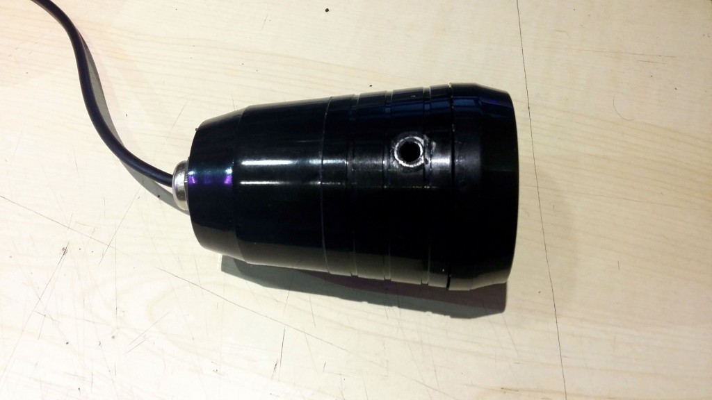
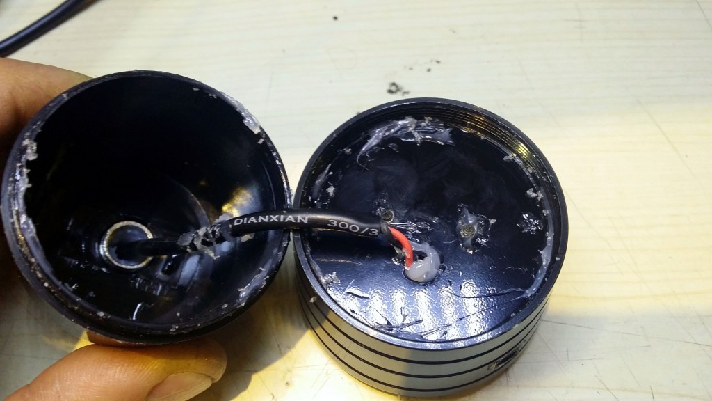
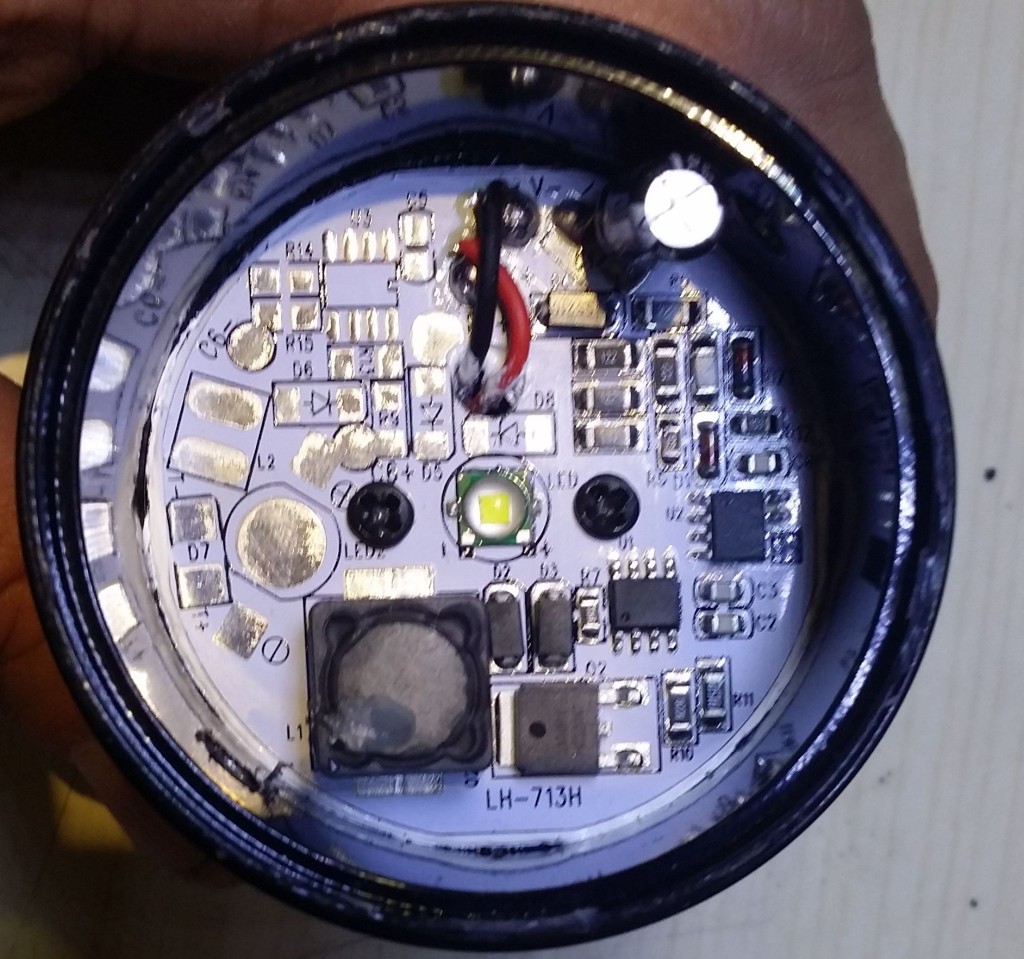
First of all, about waterproof: the whole spot is glued with a glue gun, there still exist traces of the hot glue all over the interior. This is NOT waterproof, I’d say it is at most water protected, somewhat.
The top piece holding the lens is plastic, then the body containing the PCB is aluminum, used also as radiator and the last piece is also plastic.
But let’s test the electronics. Saw this cree square Cree led, 5mm on the side. Went on Cree website, here and looked at all the square leds with 5mm sides. Only 3 were found from the XM-L family and the image of the led was in fact that of the original, simple, XM-L.
It is written on the same table that Max Light Output is 1040 lumens.
What if the light would be higher when concentrated with a lens? I had a hunch but thought to verify again.
In fact 1 lumen equals 1 cd x sr, meaning one lumen is the total light intensity measured on a solid angle of one steradian.
Quoting wikipedia, “The difference between the units lumen and lux is that the lux takes into account the area over which the luminous flux is spread. A flux of 1000 lumens, concentrated into an area of one square metre, lights up that square metre with an illuminance of 1000 lux. The same 1000 lumens, spread out over ten square metres, produces a dimmer illuminance of only 100 lux. Mathematically, 1 lx = 1 lm/m2.“
So, no, concentrating the light with a lens would not increase its lumens, as the total quantity of light, but only its intensity, measured in lux or candelas.
1st conclusion: the advertised luminous flux is 3 times lower that the real one.
I then decide to go further on testing the monster.
According to Cree’s XM-L datasheet, we have:
Forward voltage (@ 700 mA) V 2.9 3.5
Forward voltage (@ 1500 mA) V 3.1
Forward voltage (@ 3000 mA) V 3.35
Forward voltage (@ 1500 mA) V 3.1
Forward voltage (@ 3000 mA) V 3.35
Measuring the forward voltage on the led itself reads 3.02V, so, according to the datasheet, the current on the led is somewhere around 1-1.1Amps, giving a total power of 3-3.3W. Counting a factor of 85% of the power source this would raise the total power to 3.88W, less than half than the advertised 10W.
Measuring the whole circuit gives .89Amps @11.55V, meaning 10.27W.
2nd conclusion: we have 6.4W out of 10.27 (62%) lost as, I believe, heat.
The problem with low, high and pulsing beam.
Who in his right mind would wish to cycle between low-high-pulsing beam while riding a motorbike? I could (hardly) understand this behavior on a regular bicycle, but on a motorbike? No way!
The point now is to have the damned thing light only on high beam without too much damage to that aluminum PCB.
There are 3 interesting parts on the PCB:
– an IC without any markings;
– an IC saying LJY5200;
– an IC resembling to a mosfet, stating LN10N10.
The LN10N10 is indeed a 10 Amps, 100Vdc Mosfet.
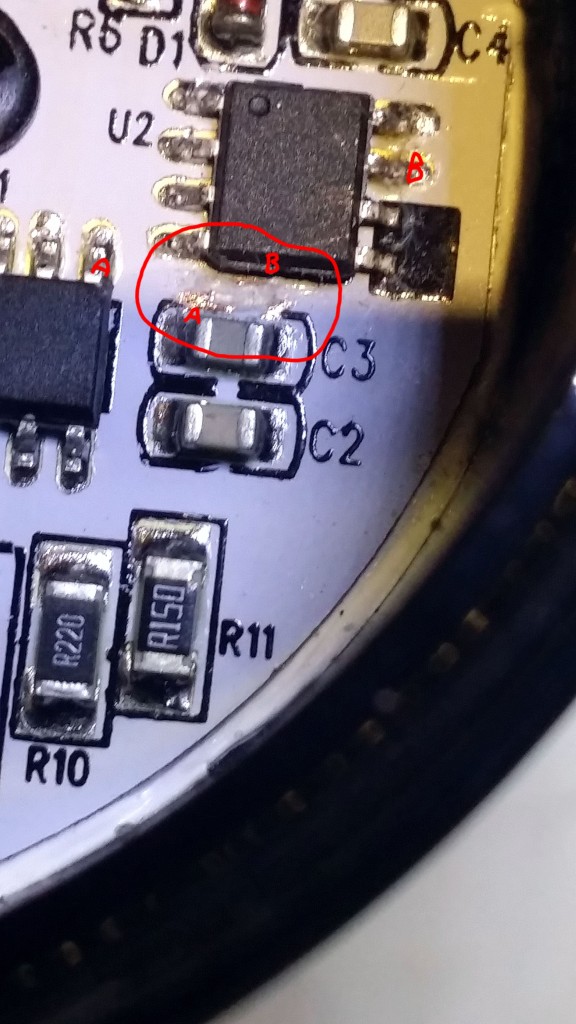
The LJY5200 is a step-down constant current led driver IC. According to its datasheet (in Chinese, hourrah Google for translating), a PWM signal between 0 and 4V on the 5th pin allows for a PWM control of the whole circuit.
Pin 5 of the LJY5200 is connected to pin 7 of the unnamed IC (probably a tiny MCU of some kind writing in EEPROM the starting sequence and then applying it at power-on circulary low-high-pulsing). Cutting the link between the two ICs solves the problem: high beam every time you power on the circuit, like in the picture below. Actually, pin 5 of LJY5200 (A in the picture) is connected to the left pin of C3 and from there there is a connection to pin 7 of the mysterious IC (B in the picture). You should cut the wire that was in the red circle in the picture.
Have fun!
3 Comments
Hi! Your post is amazing! You’ve just saved me a lot of time!
You know that mine has stopped working. I think I accidentally made a breakdown voltage in the capacitor. Now I don’t know what is not working… I think it’s the MOSFET… But not sure… Any idea?
Hola, Federico,
I am sorry to hear this. The problem with that PCB is that is is aluminum-based and I don’t see a simple way to take components out of it. I do not have its schematic either, so it’s difficult to actually say anything about why it doesn’t work anymore.
I would suggest that you went too deep with cutting that wire and you accidentally connected it to the aluminum substrate, which actually inhibits the LJY5200 chip.
This is in the datasheet, pin 5 of the LJY5200 chip is defined as:
PWM 或线性输入调光端,兼做使能端
which translates into: PWM or linear input dimming side, also do enable end
Check pin 5 and, if there is a short to the ground, there’s the problem. try finding the wire from pin 5 on the pcb and cut it again very carefully as to not short it again onto the aluminum substrate.
The LJY5200 datasheet can be downloaded here , it might give you a hint onto what you did wrong.
You can translate the document from chinese using google translate.
Finally, try sending me a hi-res picture of the whole pcb, maybe I can see something on it.
Mine doesn’t have the wire on U2. The board number is LH-713H-V1. The light is put together nicer, o-ring and no hot glue.