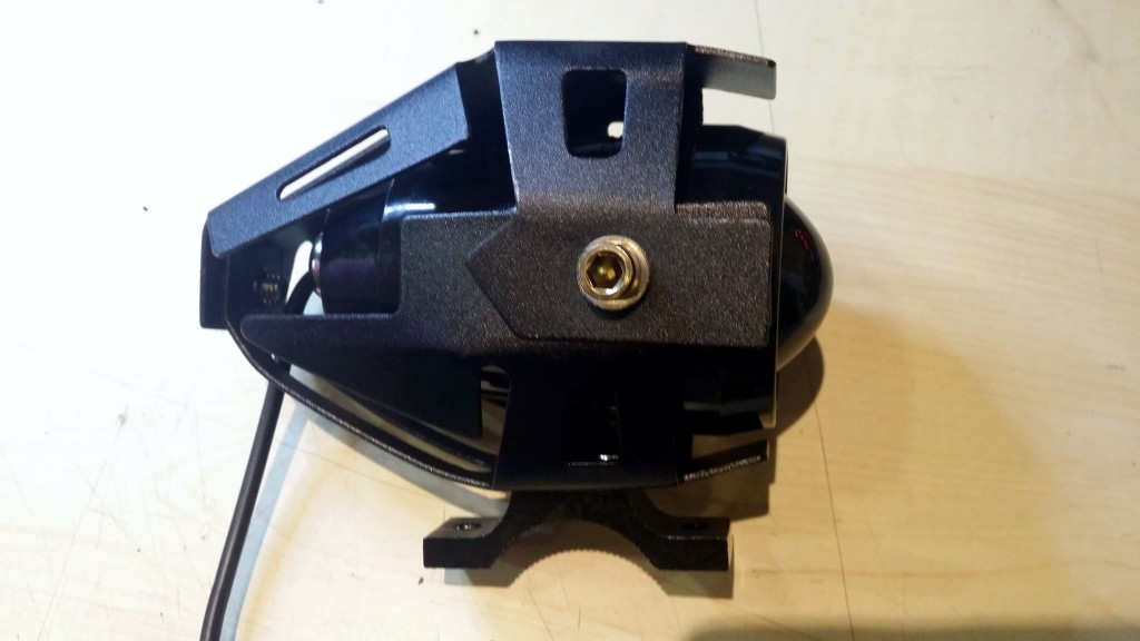
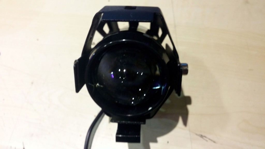
So I buy a pair of these U5 Motorcycle LED Headlight Waterproof High Power Spot Light from the Internet, to mount it on my motorbike.
Nice finish, light…hmmm…bright but not VERY, so i decide to take a look at the specs, again.
Input Voltage:12V-80V DC
Actual power: 10W
Light Power: 15W
Flux: 3000LM
Range:200 meters
LED Color Temperature:6000k-7000k
Environment Temperature: -40—40 degree centigrade
OK. 3000LM. Not quite what I saw when hitting the high beam.
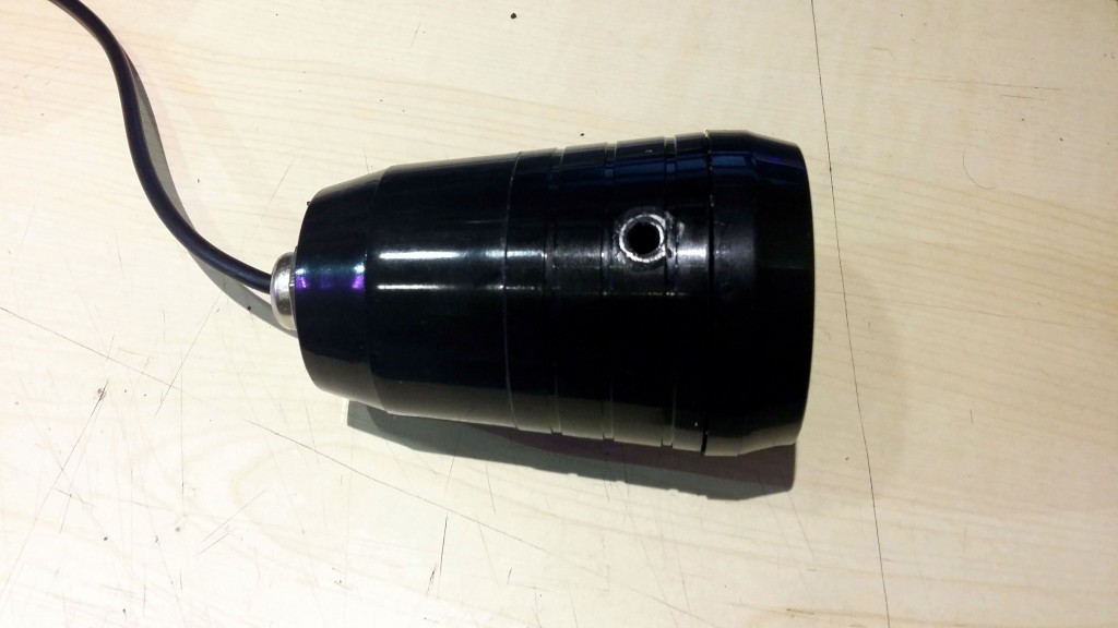
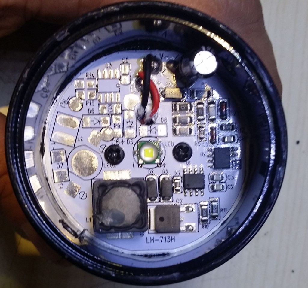
I start to disassemble the spot:
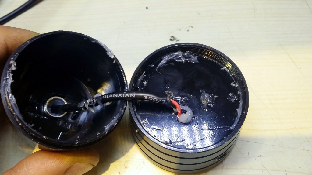
First of all, about waterproof: the whole spot is glued with a glue gun, there still exist traces of the hot glue all over the interior. This is NOT waterproof, I’d say it is at most water protected, somewhat.
The top piece holding the lens is plastic, then the body containing the PCB is aluminum, used also as radiator and the last piece is also plastic.
But let’s test the electronics. Saw this cree square Cree led, 5mm on the side. Went on Cree website, here and looked at all the square leds with 5mm sides. Only 3 were found from the XM-L family and the image of the led was in fact that of the original, simple, XM-L.
It is written on the same table that Max Light Output is 1040 lumens.
What if the light would be higher when concentrated with a lens? I had a hunch but thought to verify again.
In fact 1 lumen equals 1 cd x sr, meaning one lumen is the total light intensity measured on a solid angle of one steradian.
Quoting wikipedia, “The difference between the units lumen and lux is that the lux takes into account the area over which the luminous flux is spread. A flux of 1000 lumens, concentrated into an area of one square metre, lights up that square metre with an illuminance of 1000 lux. The same 1000 lumens, spread out over ten square metres, produces a dimmer illuminance of only 100 lux. Mathematically, 1 lx = 1 lm/m2.“
So, no, concentrating the light with a lens would not increase its lumens, as the total quantity of light, but only its intensity, measured in lux or candelas.
1st conclusion: the advertised luminous flux is 3 times lower that the real one.
I then decide to go further on testing the monster.
According to Cree’s XM-L datasheet, we have:
Forward voltage (@ 700 mA) V 2.9 3.5
Forward voltage (@ 1500 mA) V 3.1
Forward voltage (@ 3000 mA) V 3.35
Measuring the forward voltage on the led itself reads 3.02V, so, according to the datasheet, the current on the led is somewhere around 1-1.1Amps, giving a total power of 3-3.3W. Counting a factor of 85% of the power source this would raise the total power to 3.88W, less than half than the advertised 10W.
Measuring the whole circuit gives .89Amps @11.55V, meaning 10.27W.
2nd conclusion: we have 6.4W out of 10.27 (62%) lost as, I believe, heat.
The problem with low, high and pulsing beam.
Who in his right mind would wish to cycle between low-high-pulsing beam while riding a motorbike? I could (hardly) understand this behavior on a regular bicycle, but on a motorbike? No way!
The point now is to have the damned thing light only on high beam without too much damage to that aluminum PCB.
There are 3 interesting parts on the PCB:
– an IC without any markings;
– an IC saying LJY5200;
– an IC resembling to a mosfet, stating LN10N10.
The LN10N10 is indeed a 10 Amps, 100Vdc Mosfet.
The LJY5200 is a step-down constant current led driver IC. According to its datasheet (in Chinese, hourrah Google for translating), a PWM signal between 0 and 4V on the 5th pin allows for a PWM control of the whole circuit.
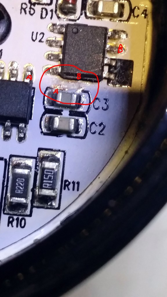
Pin 5 of the LJY5200 is connected to pin 7 of the unnamed IC (probably a tiny MCU of some kind writing in EEPROM the starting sequence and then applying it at power-on circulary low-high-pulsing). Cutting the link between the two ICs solves the problem: high beam every time you power on the circuit, like in the picture below. Actually, pin 5 of LJY5200 (A in the picture) is connected to the left pin of C3 and from there there is a connection to pin 7 of the mysterious IC (B in the picture). You should cut the wire that was in the red circle in the picture.
Please, do not post elsewhere the code found here.
– The code should reside in one place and people should use links to my site instead. I have a hard time browsing the Internet for pieces of code sometimes, and finding old or obsolete code instead of links to the original developer is always a pain in the ass.
– I expect people to comment on the code and make optimizations/new developments, especially for student usage. Having this in mind, the code itself is an ongoing process which can be followed by students, from its first state (intelligible, but unoptimized) to its latest state (optimized, but unintelligible). Many people asked me how the code becomes awful and almost impossible to understand. It is my chance to show that I always start from a human approach and I am ending to a computer approach, and that this is always an endeavour that takes time and patience and endless computations and verifications, it doesn’t just come from thin air.
– the last reason is that I collect stats on page visits and downloads, which show me where to insist with open source development and where not to. I cannot collect stats from foreign sites, nor do I wish or have the time to do so.
Bad is a nice thing to say. The firmware was horrible:
– it doesn’t show day/month/year;
– the setup is tricky and not easy to remember/understand;
– it lacks temperature;
– many people comment it is too bright during the night.
– the STC 15F204EA processor was a bad choice. 4K of flash do not suffice to build a nice and comfortable firmware for the end user, in my experience this design needs an processor with at least 8k flash.
So I decided to modify the latest firmware for the EC1204B clock and make it available for this version, with the necessary modifications.
The software/firmware presented here is a complete rewrite from scratch, just by observing the schematic and by understanding the way it works. It did not involve any kind of disassembly of the original firmware, reverse engineering or other similar stuff.
I do not condone copying the work of others in any way. However, progress is difficult to achieve these days from zero and it is easier to build up on something that already exists, while respecting the original work and effort.
I advice my readers to buy Banggood kits, the PCB has an excellent quality and all the parts delivered will be used, even with the modifications I suggest in this post. The idea is to start learning soldering and coding using affordable ressources.
2. Hardware modifications
Video 1: The modified clock
After studying the schematic, it became obvious the only thing that needed to be replaced was the processor itself, with another firmware.
I couldn’t find any Atmel processor compatible pin to pin with the original, STC 15F204EA processor. The available place to insert a custom PCB in the processor’s slot is also narrow, so space would be of the essence in choosing a replacement processor.
This is why I have decided to use an ATmega8 AU, which is the smd version of the ATmega8.
Supplementary, a DS18B20 was added to measure temperature along with a photo-transistor, to implement automatic dimming of the display.
From a mechanical point of view, the programming pins were designed to go through the plexiglass wall, in order to allow programming of the device even when it is fully enclosed, without the need to disassemble the enclosure (see Figure 3 above).
2.1 Schematic
2.2 PCB
2.3 The actual PCB
Figure 5. The bottom side of the PCB
Figure 6. The top side of the PCB
3 Software-firmware
The software, or firmware, is a variation of the software used for the EC1204B clock, in a previous post of mine.
Disregarding the process of eliminating pieces of code that did not apply to this particular clock, the two main additions are:
-the implementation of analog reading from a photo-diode, quite straightforward process;
– the implementation of digital dimming a multiplexed display.
A few words about the latter. The problem was to dim the display without having disturbing light shifts.
How it was done: In a multiplexed display, only one digit is lit a a time, with the specific data for that digit. Then, we go to the second digit and so on until the last. Basically we have an eternal cycle of lighting each digit at a time, cycle equal to the number of digits to be lit. What if we would add to this cycle “dead” times, when we don’t lit any digit? The result will be a software pwm on the multiplexed digits, up to the point when all the digits start to tremble. After a few trials, I have discovered that this has to stop at around 50 cycles. After 50 cycles, the dimming process isn’t perceived by the human eye, but it inserts this trembling of the digits.
The relationship between the level of light and the dimming is a simple transformation of the first degree, where dimming is inversely proportional to the level of light. The actual parameters are decided by experimenting. In this particular case, I had:
0 light -> 50 dimming cycles
50 light -> 4 dimming cycles.
The transformation became : cycles = (54-light), which is a rough approximation of the hypothesis above. A supplementary condition is also in effect, after reading the light value:
if (light>50) light=50;
This was necessary from direct observation: at 50 light, the display was too dimmed and the light value (0-100) didn’t correspond well with the dimming if it was to be used full scale.
Feel free to play with the code and try to modify and optimize it. I hope it is easy enough to understand after 1-2 hours of study, in its most intimate details.
4. How it works
The upper button is the “set” button. The lower button is the “select” button.
Pressing the Set button will cycle between the DS18B20 temperature sensors present at start up. On the board there is only one sensor, but you may solder several other sensors, all connected in parallel, and the device detects them at start up.
Pressing the Select button will enable you to program the microcontroller:
A short press (less than 5s) will show the date and month. Pressing it again will show the year. One more press reverts to clock display.
A longer press (6-10s) will enter the alarm set mode. Press set to cycle between alarm hour, minutes, alarm enable and memory storage. Press select at each stage to cycle possible values (0-23 for hours, 0-59 for minutes, on/off for enable);
A longer press (11-15s) will enter the clock set mode. Press set to cycle between year, month, day, minutes, hours and memory storage. Press select at each stage to cycle possible values;
A longer press (16-20s) will enter display mode. Press set to cycle between on, off and memory storage. Press select at each stage to cycle possible values;
A longer press (21-25s) will enter the temperature unit select mode. Press set to cycle between C,F and memory storage. Press select at each stage to cycle possible values;
At each stage, the last select key press is the memory storage. After storing selected parameters, the clock will beep. If you fail to store parameters (i.e. you do not press the button), the parameters will be in effect until the next reset of the clock.
5. Download
All the project for Atmel Studio 4, including a PDF with the PCB printout and necessary datasheets for parts (DS1302, DS18B20) can be downloaded here.
Following Bob Pike’s request to have the firmware show temperatures in F instead of C, the code was modified with the possibility to program the temperature display unit. The latest version can be downloaded here.
Last edit: 18.04.2015
6. Semi-automatic software drift compensation
Many people (including me) complain about the DS1302 drift, related to badly manufactured quartz resonators that do not offer a real 32 kHz (32768 Hz) clock.
The drift may become so big, a clock can have easily +- 10 minutes drift in a matter of months. Having two or more clocks in different rooms may easily lead to headaches in the morning when the decision to leave for work becomes a growing pain week after week.
The best practice would be to insert a trimmer capacitor in series with the quartz and set it to obtain a 32768 Hz clock. Even this practice is prone to errors due to:
– bringing a metallic screwdriver next to the trimmer alters its capacity. After setting the trimmer it would change its capacity again, hence the clock;
– normal trimmers are influenced by temperature. Just a little, but enough to generate a 1-minute drift every month or so;
– usually there is no or very little space on the PCB to insert a trimmer properly;
– the DS1302 clock could stop if a trimmer inserted in the circuit.
I have imagined a software solution to the drift, by calculating it in between two clock settings.
I began by asking myself what would be a disturbing drift, and I came with 5 minutes per year at a minimum, as being disturbing. However, setting the clock every year wouldn’t be too much to do, since I already set the clock twice a year when the daylight saving time appears and disappears.
5 minutes per year would mean a drift of roughly 5*60/12=25 seconds a month, less than 1 second per day.
Since the setting is done manually and one could press the set button with a 1 second drift, if the setting would be done after 20 days, it would lead to a supplementary error drift of 365/20=18.25 seconds a year, which is less than a minute per year: it wouldn’t even be noticeable.
The whole idea is to set the clock twice in the same month from a good time source (like your PC, after synchronizing its time with a time server). Why during the same month? Just to make the subroutine that computes time difference easier and less flash consuming. Anyway, there’s less than 1K of flash available for this with this project.
So: you set the clock on the 1st of the month and then you set it again on the 20th or 30th of the month.
The software computes the time difference from the two settings, which were made using a good time source and it will also compute the time difference the DS1302 has run, thus determining the time drift in a given period of time (let’s say 34 seconds in 28 days).
28 days equal 28*24*60=40320 seconds
So we have a drift of 34 seconds every 40320 seconds, which means a drift of 1 second every 1185(.88) seconds.
The clock will remember this drift and the processor will either add or subtract (depending on whether the drift is positive or negative) one second every 1185 seconds, by reading and rewriting the seconds in the DS1302.
Two errors are now in place:
– a 0.88 second (from rounding 1185.88 to 1185) every 40320 seconds, leading to roughly 12 seconds a year: almost non existent;
– a supplementary error drift from manipulation of the setting button of 365/20=18.25 seconds a year: almost non existent either;
In fact, this kind of semi-automatic drift compensation can lead to an error of at most 30 seconds a year, much lower than we could obtain by inserting a trimmer and setting it to achieve a 32kHz clock for the DS1302. We would experience annoying drifts in 10 years of non-stop operation of the clock.
What if we set the clock in different months? The software compares the month and the year of the last setting and the previous one. If these do not match, the clock drift is set to zero and there is no automatic drift compensation. A new clock setting in the same month would trigger a new drift computation and automatic drift compensation.
What if we set the time more than once during the same month? The software would take into consideration the last interval between two settings. If the interval is too low (e.g. 3 days) it could lead to a wrong computation of the drift compensation.
In order to set the drift compensation to zero, please operate two consecutive settings one after the other or by changing the month or year.
This version of the firmware can be downloaded here.
7. Bug fixes, additions and optimizations
While working on my other project, the EC1204B Led rotating clock and implementing some requests from my readers, I have discovered ways to improve the code and also minor bugs that were addressed.
the code to multiplex the data on the display was optimized;
there was a bug while displaying temperatures over 100. It was fixed.
the colon display was modified. Now the colon displays whenever a second starts instead of displaying it on odd seconds only.
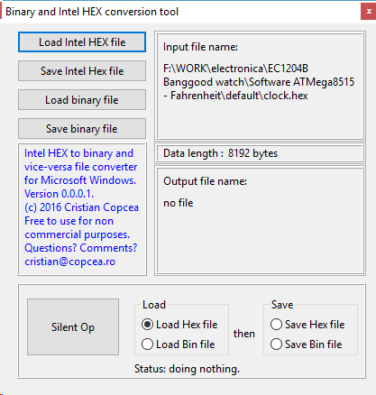
Peter Casper had a request to alternatively show the clock and the temperature, for he wishes to use the clock in an infrared-heated room.I thought using the same idea as above, so a new EEMEM variable was defined and if at programming time it is equal to 1, it fires a condition in the main loop that shows the temperature for 1 second every 10 seconds. It displays just with one (or the first) temperature sensor.Some optimizations to the display routine were also made.Because this firmware is about to hit the available flash memory in the mega8515, I had to look closely of the size of the binary data that was about to be burned into the MCU. How to do this, since the HEX file size has nothing to do with the size of the binary code? I have written this morning a Windows tool that converts Intel HEX files to binary and viceversa + it allows for automation…well, silent repetition of a load and save operations. I know, I am lazy, that’s why I wished for automation. Find what it is all about in this post.This version of the firmware can be downloaded here.
8. Combining all latest developments in one and allowing for setup without the need to reprogram the flash
While working on the latest requests for US mode (12H display and Fahnrenheit instead of Celsius), I used EEPROM variables to shorten the code and allow for its implementation. Unfortunately, to change these modes, the clock needed to be reprogrammed.
After many optimizations, I have succeeded to implement a way to set these modes without the need for a programmer.
Toggle between US and EU mode is now done from the menu itself:
EU mode displays 24H and Celsius. Setting the clock and alarm shows 24H.
US mode displays 12H and Fahnrenheit. Setting the clock and alarm shows 12H with A or P indicator for AM/PM.
Resetting the clock while pressing the SET key will toggle between regular clock display and clock/temperature display (temperature is displayes for 1 second every 10 seconds).
Enjoy downloading the latest firmware, datasheets etc, here.
At this moment, the firmware has 8160 bytes, further development on this firware being almost impossible, at least with the ATmega8.
9. It becomes a never ending story, huh?
Following the latest developments on the EC1204B clock, a new set of improvements to the code were added:
the code was optimized, again, to lower its size;
the ghost digit disappeared;
the clock can measure now negative temperatures on both C and F;
toggling between EU and US modes may also be done by keeping SET pressed at startup. It can also be changed from the menu.
Enjoy downloading the latest firmware, datasheets etc, here.
EC1204B Led Rotating Clock: Schematic, upgrade, firmware
0. Foreword
Please, do not post elsewhere the code found here.
– the code isn’t ready yet:
– I wish to develop more with several DS1621 sensors on a cable, in order to collect more than one temperature;
– The code should reside in one place and people should use links to my site instead. I have a hard time browsing the Internet for pieces of code sometimes, and finding old or obsolete code instead of links to the original developer is always a pain in the ass.
– I expect people to comment on the code and make optimizations/new developments, especially for student usage. Having this in mind, the code itself is an ongoing process which can be followed by students, from its first state (intelligible, but unoptimized) to its latest state (optimized, but unintelligible). Many people asked me how the code becomes awful and almost impossible to understand. It is my chance to show that I always start from a human approach and I am ending to a computer approach, and that this is always an endeavour that takes time and patience and endless computations and verifications, it doesn’t just come from thin air.
– the last reason is that I collect stats on page visits and downloads, which show me where to insist with open source development and where not to. I cannot collect stats from foreign sites, nor do I wish or have the time to do so.
I have built the first one in ~3 hours and spent another ~6 hours to tutor a pupil of mine into soldering the second one.
The 3rd one had a badly burned firmware and didn’t want to start. Banggood will replace it, but I thought to spend some time and rewrite the firmware, since there were some things in the original firmware I didn’t like and I wished to improve.
Figure 1. Original EC1204B Led Rotating Clock
Moreover, what is the point in having a soldering kit without having the firmware and playing for hours with it afterwards, making modifications to the firmware and learning both soldering and programming?
So, I have decided to make this project and to turn it over to the community. Teachers will have a starting point to use this interesting and cheap kit to tutor their pupils.
More advanced hobbyists will have a full working example, using the excellent PCB coming with the kit.
The whole programming stuff took me 8 full days, including the time to write and post this article.
Later edit:
It took me 8 days to finish the first version, 16 days to the first working one, including errors, modifications and improvements suggested by Philipp Klaus and Sergey, with their kind comments.
Much later edit: After almost two years I still have found improvements to the code.
Disclaimer:
The software/firmware presented here is a complete rewrite from scratch, just by observing the schematic and by understanding the way it works. It did not involve any kind of disassembly of the original firmware, reverse engineering or other similar stuff.
I do not condone copying the work of others in any way. However, progress is difficult to achieve these days from zero and it is easier to build up on something that already exists, while respecting the original work and effort.
I advice my readers to buy Banggood kits, the PCB has an excellent quality and all the parts delivered will be used, even with the modifications I suggest in this post. The idea is to start learning soldering and coding using affordable ressources.
Video: Modified EC1204B clock, latest version.
2. Modifications to the original schematic
First of all, the kit contains a few spare parts, that we will use to make the actual modifications to the clock.
Why modify the kit?
The clock is powered by an AT89S52 processor, which is an enhanced version of the classic Intel 8051. Pin to pin compatible, this processor is capable of running much faster than the original i8051. However, finding a nice development interface (IDE) and a good programmer for it is quite difficult. So, why not use more a more modern processor?
I found the AT90S8515 as being pin to pin compatible with the AT89S52, with minor differences:
– pins 29, 30 and 31 which have different functions. These pins are not used anyway, so no modifications required here.
– the reset pin (pin 9) is active high on the AT89S52 and low on the AT90S8515. So, a first modification would be required here.
– Pins 12 and 13, tied to the micro switches, should be pulled up with resistors, in order to minimize noise on these pins.
– AT90S8515 runs at 8MHz maximum while the original AT89S52 works at 12 MHz.
Figure 2.Modifications to EC1204B Led Rotating Clock
The modifications are written on the picture, but I will enumerate them here one more time:
1. Cut wiring on PCB, removing the link from the reset switch to VCC.
2. Solder a piece of wire as shown, linking the reset switch to GND.
3. Desolder C5 and R21. Solder R21 at the place of C5, building a pull-up resistor for the reset pin.
4. Do not solder anything at the place of R21. A capacitor on the reset pin will make the processor unprogrammable through ISP (in-system programming), since the RST signal is handled by the programmer.
5. Solder two resistors between 4.7Ko and 10Ko as shown, in order to pull up the SET and SELECT signals. The kit provides for 3 extra 10Ko resistors. I have used 5.6Ko resistors just because the other ones were not at hand at the time I have make these modifications.
6. Desolder the 12MHz quartz and replace it with an 8 MHz one. AT90S8515 will not run consistently (or will not run at all) at 12 MHz.
Later edit: Don’t do it at home! I wondered for quite some time how an overclocked Atmel processor would perform. So I reverted to the original 12MHz crystal, closed my eyes and powered the circuit after defining the new frequency in the software and recompiling it. Surprise! It really worked!
After a few days, though, I saw some glitches:
– mode 9 of displaying seconds doesn’t work as expected – the leds are completely crazy;
– the connection with “some” DS18B20 stop working after a while: the display shows always 127 (communication error). They start working again after a reset, so…
Still, the processor is as cold as before and, if you’re not too bothered by these two issues, you can test it for several months and post your experience here.
Figure 3. EC1204B Led Rotating Clock with AT90S8515 micro controller
At this time, the clock is ready to be connected to an external programmer. I have used an STK500:
Figure 4. Modified EC1204B Led Rotating Clock connected to a STK500 development board
Whichever programmer you wish to use, you need wires to link the programmer’s signals to the clock’s programming pins. The clock’s PCB is clearly marked with all the signals: GND, RST, SCK, MISO, MOSI and VCC.
Grab Atmel Studio 4 from Atmel’s website , WinAVR from SourceForge , configure Atmel Studio to use WinAVR toolchain, load the project below, burn it into your processor and, voilà!
3. Modus Operandi (How It Works)
Video 1: EC1204 Modus Operandi
This operation manual was updated on 26.02.2017, following the many additions to the firmware during the last two years. All timigs were also recomputed during this rewrite of the operation manual.
Definitions:
SET key: the left key
SELECT key: the middle key
RESET key : the right key
A. Special Startup Mode: Seconds Led Design
Keep pressing both SELECT and SET keys then press shortly RESET. Depress the SELECT and SET keys. You are now into Seconds Led Design menu.
Pressing SELECT, you will see numbers from 1 to 9 corresponding to the 9 ways seconds can be displayed by the circular leds. The leds show a live preview for every display mode.
Pressing SET , the selected mode will be written to memory and you will hear a confirmation beep. The selected mode will be in effect after a power off of the clock
Not pressing any key will revert to Clock Mode after about 10 seconds but the selected mode will not be written to memory, preserving it just until the next reset or power toggle.
B. Special Startup Mode: EU or US mode
Keep pressing the SELECT key then press shortly RESET. Depress the SELECT key. This will toggle between European (EU) and United States (US) modes and will affect the way the clock is displaying information:
EU mode: the clock displays 24h time and temperature in Celsius;
US mode: the clock displays 12h time and temperature in Fahrenheit;
C. Special Startup Mode: temperature toggle every 10 seconds
Keep pressing the SET key then press shortly RESET. Depress the SET key. This will toggle between regular time display mode and a mix of time and temperature. In the latter case, the clock displays the time, except for 0,10,20,30,40 and 50 seconds when it will display the measured temperature for one second. This mode was requested and it can be used in rooms or locations where a visual display of the temperature is important: saunas, datacenters etc.
Only the temperature of the first sensor is displayed in this mode.
D. To Show The Temperature
While in clock mode, short press SELECT. This will trigger the temperature mode, displaying it for all connected temperature sensors in a loop.
First, the sensor number will be displayed: “tE: 1”. A second press on SELECT will display the corresponding temperature for the first sensor.
If there are multiple DS18B20 sensors connected to the clock (maximum is 5 sensors), pressing SELECT again will display in order “tE: 2” then pressing select again the temperature of the second sensor and so on, in a loop.
EC. To Show The Day, Month and Year
While in clock mode, press SET and depress it as long as “dAtE” is displayed on the screen (<5 seconds). The month and day will be displayed for about 2 seconds.
Alternatively, pressing SET in this mode, you don’t have to wait for “dAtE” to be displayed. A short press will suffice.
Press SET again and the year will be displayed for about two seconds.
Press SET again and the clock will show the time.
D. To Set The Alarm
While in clock mode, press SET and depress it as long as “S :AL” is displayed on the screen (6-10 seconds).
First you may change the minutes of the alarm by pressing SELECT.
Pressing SET again will display the alarm hour.
You may change the hour of the alarm by pressing SELECT.
Pressing SET again will display “on” or “oFF” depending on the value read at start time from the EEPROM.
You may change if the alarm is on or off by pressing SELECT.
Pressing SET again will write the alarm values into EEPROM and the you will hear a confirmation beep.
Not pressing the final SET will change the alarm time, but it won’t be memorized in EEPROM. Thus, a power toggle or a RESET will revert alarm time to whatever was stored in EEPROM.
E. To Stop The Alarm
Just press either SET, SELECT or RESET to stop the alarm until the next time match will occur. If no button is pressed, the alarm will keep beeping for about 10 minutes.
F. To Set The Time
While in clock mode, press SET and depress it as long as “S :CL” is displayed on the screen (more than 10 seconds).
First you may change the year by pressing SELECT.
Pressing SET again will display the month.
You may change the month by pressing SELECT.
Pressing SET again will display the day.
You may change the day by pressing SELECT.
Pressing SET again will display the minutes.
You may change the minutes by pressing SELECT.
Pressing SET again will display the hour.
You may change the hour by pressing SELECT.
Pressing SET again will write the set time into DS1302 and the you will hear a confirmation beep.
Not pressing the final SET will discard all modifications made and the clock will revert to the previous settings.
Every step has a 10 seconds timeout. Not pressing any key during this interval will revert the clock to time display mode. All the settings will be lost.
4. Firmware
The code is (almost) fully commented,, because I wanted to make it easy to read, easy to understand, and a possible start for a programming course example.
What can a pupil learn from this nice clock?
Hardware:
– How to solder both through-hole and SMD components, by hand;
– How to arrange for parts on both sides of a PCB and solder them, taking into account the height of each part.
– How to find the best spots to make modifications on a given PCB.
Software:
– How to deal with the special registers of a micro controller;
– How to enable/disable interrupts;
– How to multiplex data on a large bus (12 bits) using interrupts;
– How to use variables, constants, #define and EEPROM variables and to grasp the difference between them;
– How to build custom menus for a given task;
– How to make variables prisoners between two given values;
– How to use 1-wire and 3-wire communications;
– How to dynamically program ports for input or output;
– How to write nice and clean code, easy to debug; The RTC library is a bad example of how to write a library.
– How to program a basic alarm which can be shut off;
– How to deal with bitwise operations. I wrote the program specially using |,||,~,^,&,&&,_BV(), binary and hex values, to show the many ways an operation could be done.
-How to use local and global variables;
I am sure a good tutor will find several other stuff to dissect and learn to willing pupils. The main code is almost fully commented for a better understanding.
The AVR GCC library I have used was written by Davide Gironi and I have made minor modifications on it. Please consult his work at http://davidegironi.blogspot.com
The code takes almost all the AT90S8515 flash memory (7.51K out of 8K available), so there is place for small modifications.
There is also place for improvements, if one is interested enough.
Another candidate to replacing AT89S52 would be an ATMega8515, which can run at 16 MHz instead of 8MHz when driven with a crystal. This processor is also able to run at 8MHz with an RC internal oscillator. If programmed as such, we don’t need the crystal and the two capacitors anymore!
I know there is also an other candidate from the ATMega family, compatible pin to pin with AT89S52, but I let to you the burden to browse through datasheets and discover it 😉
All the project for Atmel Studio 4 can be downloaded here. It contains an error, see 7. Errata
The schematic of the EC1204B clock can be downloaded here.
uint8_t bb(uint8_t in11, uint8_t sec1, uint8_t sec2) //function to reduce the code
{
    return dectobin(seconds-in11*8)*((seconds>= sec1) && (seconds<= sec2));
}
and transforming the line into
d[10]=0b00010000 | bb(in1,0,7);
makes the code drop from 7.6Kbit to 6.5 Kbit.
While the original code would not fit into an ATMega8515, because of the loader which takes some place in the flash, the optimized code fits entirely and there is some space left for further coding.
Improvement #2
Going further ,taking all the block of lines similar to
repeating the whole process in all the program, makes the code drop again from 6.5 Kbit to 5.86 Kbit.
With just two functions related to the way we display seconds, the code dropped with an astounding 1.74K (21%).
Unreadable code, but no less much smaller than the original!
I dare you to try reducing the code to 4K, while keeping all its features!
7. ERRATA
The code above (clock.c) contained an error related to DS1302: instead of using dt.date, I have used dt.day. Thus, reading and writing the date showed and wrote in fact the day of the week.
This error has been addressed below.
8. More Modifications And More Learning
While looking at the kit, there is something missing on the PCB: a 4-pin connector marked “bluetooth”.
Pin 1: connected to pin 10 of the processor
Pin 2: connected to pin 11 of the processor
Pin 3: GND
Pin 4: VDD
According to the datasheet, Pin10 is RxD and Pin11 is TxD of the embedded UART (AT90S8515) or USART (ATmega8515).
I remembered those HC-05 or HC-06 bluetooth modules available on the market and I realized the producer already thought to a further development of the kit, probably the possibility to set its parameters through bluetooth, from a phone.
While this is an interesting development, it doesn’t imho add too much to a learning curve. It just augments the addiction young people have today to smart phones.
Why not put his connector to a better use?
I had at home some DS1621 digital temperature chips, working on I2C.
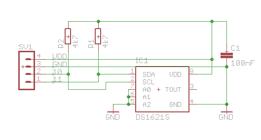
So, I have created the following schematic:
Figure 5. Schematic for a DS1621 addon card.
I fitted the board with the help of two 4-pin male and female connectors to the clock’s board and started to write code.
What is so interesting in this DS1621 chip? Well, nothing special. It is just another thermometer, using I2C communication.
What is special is the fact that ATmega8515, which I have used for this modification:
a) does not have a hardware Two Wire Interface (or TWI) that could be used for I2C communication. Thus, a bit banged library had to be used (a library which recreates by software a whatever protocol, instead of relying on hardware).
b) it can be programmed to run out of its own internal 8MHz oscillator, meaning that the 8MHz crystal I had to changed may be removed permanently.
c) may be clocked by crystals of up to 16MHz, so we could resolder the original 12 MHz crystal (while I don’t see the point of doing this).
In order to maximize speed, an assembler code had to be used. Thanks to Peter Fleury, who has already wrote this library years ago, the implementation became suddenly much easier.
The new project for Atmel Studio 4, which includes the I2C (orTWI) and the DS1621 AVR GCC libraries can be downloaded here.
– if the minutes are odd, we light every led until the current lit led equals the current second, then we turn off all other leds, one by one
– we wait for 700 microseconds
– if the minutes are even, we turn off every led until the current lit led equals the current second, then we lit all other leds, one by one
– we wait for 700 microseconds
The total computing time reaches ~90 milliseconds, there is a rest of 10 milliseconds to have a delay between seconds.
These delays over delays have a negative impact on the way the clock works, especially if another execution thread comes into action:
– the alarm sounds like crap;
– setting the clock becomes a pain in the a** because short key presses are almost never felt, since the clock is “waiting for time to pass”.
This led me to reconsider the approach and to try to eliminate the delays, without having a strong visual impact.
9.2 Second and final attempt
Since the display and the leds are multiplexed, and the timer overflow code runs again and again (in fact it runs 1024 times a second), why not use a counter to see how many refreshes were made, divide this counter by 13 and use the result? Why 13? Well, 1024/24=78. We could use the first 60 numbers (0-59) to light up the corresponding led, and wait during the numbers 60 to 78.
This approach would solve more than one issue:
– the delay between two leds is determined by the setting of the timer itself, i.e. by hardware, instead of software (delays);
– the delay between two leds is very precise, since we don’t do for cycles anymore.
– the delay between the end of the last led and the following second is very precise;
– we don’t use delays anymore, so reading keys and sounding an alarm will perform as good as in the other modes of seconds display (1 to 8).
– the processor is processing slightly more than in the first case, when it had to process A LOT.
The second form of the same function is the following:
     case 9:
            j=refresh/13;
            if (odd(dt.minute))
            {
                if (j<=seconds)
                {
                    in1=j/8;
                    fillbefore(in1,0xFF);
                    d[in1+10]=p2(j-in1*8);
                    fillafter(in1,0x00);
                }
            }
            else
            {
                if (j<=seconds)
                {
                    in1=j/8;
                    fillbefore(in1,0x00);
                    d[in1+10]=~p2(j-in1*8);
                    fillafter(in1,0xFF);
                }
            }
            break;
There is an issue though: the refresh/13 and the start of a new seconds are almost certainly not in phase. Resetting the refresh counter at 1024 does not mean it will be reset at the same moment a new second is coming. This leads to a shift between showing the seconds dots and displaying the seconds leds. When the seconds reach 59 and before changing to zero again, part of the leds don’t lit anymore.
The solution was to reset the refresh counter at the same time the read second from the DS1302 changed. This was accomplished in the timer overflow routine with a simple code, as follows:
ISR(TIMER1_OVF_vect)
{
    uint8_t PV;
//comment up to the next sign in order to use first version of function for seconds #9
//    |
//    |
//    v

    refresh++;
    timestamp1=seconds;
    if (timestamp1==timestamp2)
    {
        if (!refresh_resetted)
        {
            refresh=0;
            refresh_resetted=1;
        }
    }
    else
    {
        refresh_resetted=0;
    }

//    ^
//    |
//    |
//comment from the first sign in order to use first version of function for seconds #9

    switch (digit_addressed)

... blah blah the same thing as in previous versions

    if(digit_addressed>=12) digit_addressed=0;
//comment the following line in order to use first version of function for seconds #9
//    |
//    |
//    v

    timestamp2=dt.second;

//    ^
//    |
//    |
}
I have discovered a few errors in the firmware (delays not working) and also typos in this very article.
I wrote also a couple of supplementary functions to lower the code size.
Enjoy downloading the latest firmware, datasheets etc, here.
Comment with your ideas, findings etc.
10. Pulsing display
While setting the alarm or the clock, the display should pulse.
With the current firmware, this doesn’t happen.
How to solve this issue without a too big overhead?
Because we are counting refresh cycles, we could display the useful digits on the first half (up to 512) and display the NULL symbol on the second half.
We define two new variables:
uint8_t pulsing=0, showdigit=0;
then we alter the Timer Overflow routine, the part pertaining to digits display:
    if (pulsing) showdigit=(refresh<512); else showdigit=1;
    switch (digit_addressed)
    {
        case 0:
        PV=PORTD;PV &= ~_BV(4);PV |= _BV(5);PV |= _BV(6);PV |= _BV(7);PORTD=PV;
        if (showdigit) PORTA = ~(d[0]); else PORTA= ~(SEG_NULL);
        PORTC=0xFF;
        break;
        case 1:
        PV=PORTD;PV |= _BV(4);PV &= ~_BV(5);PV |= _BV(6);PV |= _BV(7);PORTD=PV;
        if (showdigit) PORTA = ~(d[1]); else PORTA= ~(SEG_NULL);
        PORTC=0xFF;
        break;
        case 2:
        PV=PORTD;PV |= _BV(4);PV |= _BV(5);PV &= ~_BV(6);PV |= _BV(7);PORTD=PV;
        if (showdigit) PORTA = ~(d[2]); else PORTA= ~(SEG_NULL);
        PORTC=0xFF;
        break;
        case 3:
        PV=PORTD;PV |= _BV(4);PV |= _BV(5);PV |= _BV(6);PV &= ~_BV(7);PORTD=PV;
        if (showdigit) PORTA = ~(d[3]); else PORTA= ~(SEG_NULL);
        PORTC=0xFF;
        break;
        ...the rest of the function is the same as before
The main routine has also to be altered, in order to set the modes where we wish the display to be pulsing or not:
        //we are focusing on this part of the main function, deciding what to display when there is no key pressed (free running clock)
        //and we add for each display mode a line stating whether we wish a pulsing display or not
        if (key==0)
        {
            //void all long key presses
            switch (ClockMode)
            {
            case SHOWCLOCK:
                if (t2==0)
                {
                    //show clock
                    pulsing=0;
                    dt=get_date_time();
                    digit=dt.hour*100+dt.minute;
                    seconds=dt.second;
                }
                else
                if (t2<=5)
                {
                    //show the date
                    pulsing=0;
                    t1=6000;
                    t2=0;
                      dt=get_date_time();
                    seconds=dt.second;
                    ClockMode=SHOWDATE;
                }
                else
                if (t2<=10)
                {
                    //set the alarm
                    pulsing=1;
                    t1=900;
                    t2=0;
                      dt=get_date_time();
                    seconds=dt.second;
                    ClockMode=SETALMINUTES;
                }
                else
                {
                    //set the date
                    pulsing=1;
                    t1=900;
                    t2=0;
                    dt1=dt;
                    ClockMode=SETYEAR;
                }
                break;
            case SHOWTEMP:
                //show temperature until timer expires
                //digit = ds18b20_gettemp();
                pulsing=0;
                digit = get_ds1621_temperature();
                  dt=get_date_time();
                seconds=dt.second;
                _delay_ms(10);
                break;
            case SHOWDATE:
            //show the date
                pulsing=0;
                dt=get_date_time();
                digit=dt.month*100+dt.date;
                seconds=dt.second;
                _delay_ms(1);
                break;
            case SHOWYEAR:
            //show the year
                pulsing=0;
                dt=get_date_time();
                digit=2000+dt.year;
                seconds=dt.second;
                _delay_ms(1);
                break;
            case SETHOURS:
                pulsing=1;
                  dt=get_date_time();
                seconds=dt.second;
                _delay_ms(10);
                break;
            case SETMINUTES:
                pulsing=1;
                  dt=get_date_time();
                seconds=dt.second;
                _delay_ms(10);
                break;
            case SETDATE:
                pulsing=1;
                  dt=get_date_time();
                seconds=dt.second;
                _delay_ms(10);
                break;
            case SETMONTH:
                pulsing=1;
                  dt=get_date_time();
                seconds=dt.second;
                _delay_ms(10);
                break;
            case SETYEAR:
                pulsing=1;
                  dt=get_date_time();
                seconds=dt.second;
                _delay_ms(10);
                break;
            case SETALHOURS:
                pulsing=1;
                  dt=get_date_time();
                seconds=dt.second;
                _delay_ms(10);
                break;
            case SETALMINUTES:
                pulsing=1;
                  dt=get_date_time();
                seconds=dt.second;
                _delay_ms(10);
                break;
            case SETAL:
                pulsing=1;
                  dt=get_date_time();
                seconds=dt.second;
                _delay_ms(10);
                break;
            case SETSECMODE:
                //read seconds to be displayed
                pulsing=1;
                dt=get_date_time();
                seconds=dt.second;
                _delay_ms(10);
                break;
            default:
                break;
            }
        }
        else
        //set key was pressed
        if (key==1)
        {
            if (AlarmOn)
            {
                AlarmOn=0;
            }
            switch (ClockMode)
            {
            case SHOWCLOCK:
                //set to SHOWTEMP and set the timer to ~10 seconds
                t1=900;
                ClockMode=SHOWTEMP;
                break;
            case SHOWTEMP:
                //nothing to do
                break;
            case SHOWDATE:
                break;
            case SHOWYEAR:
                break;
            case SETHOURS:
                pulsing=0;
                t1=900;
                if (++dt1.hour>MaxHours) dt1.hour=MinHours;
                break;
            case SETMINUTES:
                pulsing=0;
                t1=900;
                if (++dt1.minute>MaxMinutes) dt1.minute=MinMinutes;
                break;
            case SETDATE:
                pulsing=0;
                t1=900;
                if (++dt1.date>MaxDate) dt1.date=MinDate;
                break;
            case SETMONTH:
                pulsing=0;
                t1=900;
                if (++dt1.month>MaxMonth) dt1.month=MinMonth;
                break;
            case SETYEAR:
                pulsing=0;
                t1=900;
                if (++dt1.year>MaxYears) dt1.year=MinYears;
                break;
            case SETALHOURS:
                pulsing=0;
                t1=900;
                if (++ALHours>MaxALHours) ALHours=MinALHours;
                break;
            case SETALMINUTES:
                pulsing=0;
                t1=900;
                if (++ALMinutes>MaxALMinutes) ALMinutes=MinALMinutes;
                break;
            case SETAL:
                pulsing=0;
                t1=900;
                if (++ALSet>MaxALSet) ALSet=MinALSet;
                break;
            case SETSECMODE:
                pulsing=0;
                dt=get_date_time();
                seconds=dt.second;
                t1=900;
                if (++SecMode>MaxSecMode) SecMode=MinSecMode;
                break;
            default:
                break;
            }
        }
        else
        //select key pressed
        if (key==2)
        {
            if (AlarmOn)
            {
                AlarmOn=0;
            }
            switch (ClockMode)
            {
            case SHOWCLOCK:
                //short key press 1-5 seconds: show date/time for 10 seconds
                //long key press 6-10 seconds: enter alarm set
                //more than 10 seconds pressed: enter date set
                t2++;
                digit=t2;
            case SHOWTEMP:
                break;
            case SHOWDATE:
                t1=6000;
                ClockMode=SHOWYEAR;
                break;
            case SHOWYEAR:
                ClockMode=SHOWCLOCK;
                break;
            case SETHOURS:
                //write the time/date/year into the DS1302
                pulsing=0;
                set_date_time(dt1);
                t1=0;
                beep();
                _delay_ms(200);
                break;
            case SETMINUTES:
                ClockMode=SETHOURS;
                break;
            case SETDATE:
                ClockMode=SETMINUTES;
                break;
            case SETMONTH:
                ClockMode=SETDATE;
                break;
            case SETYEAR:
                ClockMode=SETMONTH;
                break;
            case SETALHOURS:
                ClockMode=SETAL;
                break;
            case SETALMINUTES:
                ClockMode=SETALHOURS;
                break;
            case SETAL:
                //write Alarm Values into EEPROM
                pulsing=0;
                eeprom_write_byte(&EALHours,ALHours);
                eeprom_write_byte(&EALMinutes,ALMinutes);
                eeprom_write_byte(&EALSet,ALSet);
                t1=0;
                beep();
                _delay_ms(200);
                break;
            case SETSECMODE:
                //write SecMode into EEPROM
                pulsing=0;
                eeprom_write_byte(&ESecMode,SecMode);
                t1=0;
                beep();
                _delay_ms(200);
                break;
            default:
                break;
            }
        }
        t1--;
        if (t1==0xFFFF) t1=0;
        if (t1==0) ClockMode=SHOWCLOCK;
        display();
        CheckAlarm();
        }

        ...the rest is the same
Enjoy downloading the latest firmware, datasheets etc, here.
Comment with your ideas, findings etc.
11. Multiple DS18B20 on a wire
This development took some time because I was waiting for my DS18B20 stack to arrive.
Thanks, Sergey, for commenting on my blog and giving me the necessary push to write the code.
Thanks, Philipp Klaus, for showing me the error in defining the CPU frequency. It helped a lot, especially in the 1-wire protocol, where delays are of the essence and strongly tied to the CPU frequency.
The nice little clock is able now to show up to 5 (modifiable variable) DS18B20 sensors, connected in parallel on the same wire.
The program does an automatic search for the sensors and is able to read and display the temperature of each of the sensors it finds at start-up.
Sensors can be plugged in live, while the clock is running, but to detect new sensors the clock must be reset from the reset button.
If the temperature shows at times “85C” it is because this is the initial value of the sensor.
If the temperature shows “127C” it means there is a miscommunication with that particular sensor. Check the cables, solderings etc. It might also mean the sensor is dead, in which case it needs to be replaced.
The order the sensors are discovered seems random to the end user. This order is in fact determined by the serial number of each sensor. The good thing is that the sensors are always detected in the same order if they are not changed. Their position on the wire doesn’t matter.
While adding or removing sensors, the order modifies again, but remains the same if no more sensors are added/removed after a reset or power failure. This way, in order to match the software order with the physical order of the sensors, it is enough to rearrange the position of the sensors on the wire so it matches the software detection order.
Connecting the sensors must be done by using shielded microphone cables especially for longer distances (more than 3 meters or 9 feet). An alternative would be the use of a 3-wire twisted cable. Check and see what works.
What is NOT implemented in software:
– negative temperatures (with a “-” in front of the temperature). I tried putting an ice cube onto one sensor and it got down to…1C after 5 minutes. It didn’t want to get to a lower temperature. The code is however opened to modifications.
– parasitic supply and all the other exhaustive features DS18B20 know about. I’ll leave this for whoever wishes to better the DS18B20 library. It’s not hard. It’s just that I don’t have the time to write a full library for this sensor.
– CRC8. First, it would be a software burden, bearing in mind the flash is almost full with this version of the firmware. Second, you don’t need CRC8 is your sensors are connected with shielded microphone cables of up to 3 meters. Cautin, however, in very noisy environments. Reading could be wrong.
The seconds don’t show accurately on mode 9 while performing temperature readings, mainly because the low level of the one-wire protocol are disabling and re-enabling interrupts. All other functions are working just fine.
This firmware release is not implementing the I2C protocol anymore, neither is it capable to read from the DS1621 anymore. The libraries were removed from the project in order to make space for the larger code of the main program and the new DS18B library. The files remained however in the project’s zip file.
Enjoy downloading the latest firmware, datasheets etc, here.
Comment with your ideas, findings etc.
12. Displaying Celsius or Fahrenheit units
I had a request from a US citizen to make the clock display the temperature in Fahnrenheit. I’d like to say to him a public Thank You for the donation he has made.
Since there is not much space left into the mega8515 chip with the latest additions, I wondered a few days on how to implement this but while keeping the Celsius display functionality too.
Writing a code to another menu level would have resulted in a code bigger than the available 8K of flash, so something else had to be done.
In clock.c, a supplementary definition came up:
//ECFUnit defines Celsius or Fahrenheit display
//ECFUnit=0 means Celsius Display
//ECFUnit=1 defines Fahnrenheit Display
EEMEM uint8_t ECFUnit=1;
uint8_t CFUnit;
The ECFUnit value is stored in EEPROM and it is read at init time then it is then stored in the CFUnit variable.
When the temperature is read from the sensor (in Celsius, because this is how the sensor is manufactured), the CFUnit is checked and, if it is equal to 1, it will compute the following equation:
digit=digit*9/5+32
basically transforming the Celsius value to a Fahnrenheit value.
So, switching from C to F requires a rewrite of just the EEPROM values. I guess that, depending on where one lives, one will select the display unit just once in a lifetime.
I have checked how it displays up to 255F and I have actually discovered a small hidden bug that I have also addressed.
At temperatures over 100F, the second digit disappeared if it was zero. So I checked that part of the code again handling the temperature and it looked like this:
The code made sense: if the second digit (d[5]) was zero, indeed the second displayed digit (d[1]) was set to NULL, even if the first digit was different than zero.
An interesting bug, I thought I have addressed all the small bugs until now but practice shows that tiny errors can always survive in a code.
Now, the second digit is NULL if it is equal to zero AND if the first digit is also equal to zero.
Changing the unit letter from C to F was simple. The “C” letter has an index of 12 and the “F” letter an index of 14. We should display “C” if CFUnit is equal to zero and “F” if CFUnit is equal to 1.
The index of the letter to be displayed becomes then 12+CFUnit*2.
Enjoy downloading the latest firmware, datasheets etc, here.
Comment with your ideas, findings etc.
13. Displaying the temperature every x seconds while displaying the time
Peter Casper had a request to alternatively show the clock and the temperature, for he wishes to use the clock in an infrared-heated room.
I thought using the same idea as above, so a new EEMEM variable was defined and if at programming time it is equal to 1, it fires a condition in the main loop that shows the temperature for 1 second every 10 seconds. It displays just with one (or the first) temperature sensor.
Some optimizations to the display routine were also made.
Because this firmware is about to hit the available flash memory in the mega8515, I had to look closely of the size of the binary data that was about to be burned into the MCU. How to do this, since the HEX file size has nothing to do with the size of the binary code? I have written this morning a Windows tool that converts Intel HEX files to binary and viceversa + it allows for automation…well, silent repetition of a load and save operations. I know, I am lazy, that’s why I wished for automation. Find what it is all about in this post.
Enjoy downloading the latest firmware, datasheets etc, here.
Comment with your ideas, findings etc.
14. Combining all latest developments in one and allowing for setup without the need to reprogram the flash
While working on the latest requests for US mode (12H display and Fahnrenheit instead of Celsius), I used EEPROM variables to shorten the code and allow for its implementation. Unfortunately, to change these modes, the clock needed to be reprogrammed.
After many optimizations, I have succeeded to implement a way to set these modes without the need for a programmer.
Resetting the clock with the SELECT key pressed will toggle between US and EU mode:
EU mode displays 24H and Celsius. Setting the clock and alarm shows 24H.
US mode displays 12H and Fahnrenheit. Setting the clock and alarm shows 12H with A or P indicator for AM/PM.
Resetting the clock while pressing the SET key will toggle between regular clock display and clock/temperature display (temperature is displayes for 1 second every 10 seconds).
Resetting the clock while pressing both SELECT and SET keys will enter Seconds Display Mode, where you can choose between the 9 ways to display rotating seconds.
Enjoy downloading the latest firmware, datasheets etc, here.
At this moment, the firmware has EXACTLY 8192 bytes, occupying all the flash memory available on the processor:
15. Latest optimizations and additions
Having lots of people testing the software is certainly an asset, as other may discover hidden bugs otherwise impossible to see.
It just happened to one clock that, when the power came down and up again repeatedly, the eeprom section of the clock just erased by itself.
A more in-depth look at the mega8515 datasheet states in fact eeprom corruption in special circumstances, when the voltage is slowly rising, on heavy filtered power sources, or, maybe, when power goes down and up again, leading to the same effect. The MCU executes erratic commands and the voltage is too low for proper eeprom operation, so anything can happen.
Since the code was 100% full, I had to look and identify which are the similar sections of code and write a procedure to be called insted of repeating the same lines of code. This code was identified in the menu section of the main loop. It was optimized and I got some other ~300 bytes of flash that could be used to implement an eeprom corruption prevention system.
Basically, all constants in the eeprom were defined with separate default values and a crc was implemented. Every eeprom read was checking the crc and every time an eeprom value changed, like the alarm etc, the crc was recomputed and written into the eeprom. If the crc is not the expected one while reading any eeprom value, the whole bunch of eeprom variables are reinitialized with their default values.
The important part of the code:
EEMEM uint8_t ECFUnit=0;
uint8_t CFUnit;
EEMEM uint8_t ESwing=1;
uint8_t Swing;
EEMEM uint8_t EUSMode=0;
uint8_t USMode;
EEMEM uint8_t ESecMode=9;
EEMEM uint8_t EALMinutes=0;
EEMEM uint8_t EALHours=0;
EEMEM uint8_t EALSet=0;
//ECRC and DefCRC have to be recomputed manually after a modification to any of the following eeprom variables:
//ECFUnit, ESwing, EUSMode, ESecMode, EALMinutes, EALHours, EALSet
//ECRC=ECFUnit+ESwing+EUSMode+ESecMode+EALMinutes+EALHours+EALSet
EEMEM uint8_t ECRC=10;
uint8_t DefCRC=10;
An example of modifying the default values, like if we wish for and US Mode display by default (AM/PM display, Fahrenheit for temperature) would need the modification of the following variables:
Enjoy downloading the latest firmware, datasheets etc, here.
16. Negative temperatures
This firmware does not use the floating point library, it would become huge. Thus it relies solely on integer operations, most of it unsigned.
Temperatures, however, are signed. Using several sensors and having one outside at winter should display negative temperatures, but at this point it doesn’t.
Since at the moment that I am writing these lines there are negative temperatures outside, I thought to address this final issue.
I have observed that, when the temperature was dropping under zero C, the clock was displaying temperatures counting down from 127.
This latest firmware takes negative temperatures into account and displays them correctly, both with Celsius and Fahnrenheit degrees.
Enjoy downloading the latest firmware, datasheets etc, here.
17. Timings
All the latest additions to the firmware made that some timings related to the duration some information was displayed became erroneous. This latest development addresses these errors and corrects them.
Enjoy downloading the latest firmware, datasheets etc, here.
Here you can find and download issues of MODELISM magazines (click right and SAVE AS). If you wish to consult them online, all pages will open in a new window or tab according to the browser you are using.
All files are available only in Romanian, as they are not translated.
MAGAZINES
All the files were taken at hand in january 2010 in order to:
– diminish file sizes (some magazines went up to 80MB);
– allow for text search (all pages were OCR-ised).
I hope you will find more quickly some articles and schematics.
The download speed limit was limited to ~3Mbps because the demand is higher and higher. Please be patient with downloads, finally you will download everything you need.
This collection is always prone to modifications, consisting in error elimination (huge number of files, tiredness, etc), new issues, modifications of existing files with other of a better quality, etc. This is the reason why the last page update is listed below.
Last page update: 04.09.2011
Should you wish to contribute to the effort of bringing Modelism magazine collection online, as well as for other magazine that will follow, you can donate:
ELECTRONIC ARCHIVE OF MODELISM MAGAZINE:
Sur cette page tu trouveras et pourras télécharger des numéros de la revue MODELISM (clic droit et ENREGISTRER SOUS). Si tu veux les consulter en ligne, je t’annonce que les pages s’ouvriront dans une nouvelle fenêtre ou dans un nouvel onglet, en fonction du navigateur que tu utilises.
REVUES
Tous les fichiers ont été processés en janvier 2010 pour:
– diminuer leur taille (certains numéros avaient même 80MB);
– permettre un recherche en mode texte ;
J’espère qu’ainsi tu trouveras plus vite certains articles et montages.
La vitesse de téléchargement du site a été réduite à environ 3Mbps, à cause de la demande de plus en plus importante. Aie de la pacience avec les téléchargements, finalement tu réussiras à télécharger tout ce qui t’intéresse..
Cette colelction est modifiée de temps en temps. Les modification consistent dans le déboguage (nombre immense de fichiers, lassitude etc), nuveaux numéros, modifications des fichiers existants avec d’autres de meilleure qualité (en couleur par exemple), etc. C’est pourquoi sur cette page tu verras la date de la dernière mise à jour.
Dernière mise à jour de la page: 04.09.2011
Si tu désires contribuer à l’effort déposé pour la collection MODELISM, ainsi que poour d’autres collections qui paraitront, tu peux faire une donation:
ARCHIVE ELECTRONIQUE DE LA REVUE MODELISM:
Aici puteti gasi si descarca numere din revista MODELISM (clic dreapta si SAVE AS). In cazul in care doriti sa le consultati online, va anunt ca paginile se vor deschide intr-un nou tab sau fereastra, functie de browserul utilizat.
REVISTE
In cazul in care posedati numere lipsa din colectia de mai jos sau orice numere “supliment”, va rugam sa trimiteti o copie PDF scanata la cristian.at.jointelecom.ro pentru a le pune la dispozitia celor ce au nevoie. Va multumesc.
Toate fisierele au fost reprelucrate in ianuarie 2010 pentru:
– a scadea dimensiunea acestora (unele numere ajusesera si la 80MB);
– a permite cautarea in mod text (a fost aplicat OCR pe toate paginile).
Sper astfel sa gasiti mai repede unele articole si montaje.
Viteza de descarcare de pe blog a oricarui fisier a fost limitata la cca 3Mbps, avand in vedere cererea foarte mare. Va rog sa aveti rabdare cu descarile, intr-un final veti reusi sa descarcati tot ce va intereseaza.
In aceasta colectie apar in permanenta modificari. Acestea pot consta in eliminarea de erori (datorate numarului foarte mare de fisiere, oboselii, etc), adaugiri de numere, modificari ale fisierelor existente cu altele de calitate mai buna (eventual color), etc. Din acest motiv pe aceasta pagina va aparea si data cand a fost efectuata ultima aducere la zi.
Data ultimei aduceri la zi a paginii: 04.09.2011
Daca doriti sa contribuiti la efortul depus pentru colectia Modelism, ca si pentru alte lucrari care vor mai aparea, puteti dona:
Here you can find and download issues of TEHNIUM magazines and almanacs (click right and SAVE AS). If you wish to consult them online, all pages will open in a new window or tab according to the browser you are using.
All files are available only in Romanian, as they are not translated.
MAGAZINES
All the files were taken at hand in january 2010 in order to:
– diminish file sizes (some magazines went up to 80MB);
– allow for text search (all pages were OCR-ised).
I hope you will find more quickly some articles and schematics.
Tehnium International collection was published separately to avoid interferences and confusions.
The download speed limit was limited to ~3Mbps because the demand is higher and higher. Please be patient with downloads, finally you will download everything you need.
This collection is always prone to modifications, consisting in error elimination (huge number of files, tiredness, etc), new issues, modifications of existing files with other of a better quality, etc. This is the reason why the last page update is listed below.
Last page update: 04.09.2011
Should you wish to contribute to the effort of bringing Tehnium magazine collection online, as well as for other magazine that will follow, you can donate:
ELECTRONIC ARCHIVE OF TEHNIUM AND TEHNIUM INTERNATIONAL MAGAZINES:
Sur cette page tu trouveras et pourras télécharger des numéros de la revue et des almanachs TEHNIUM (clic droit et ENREGISTRER SOUS). Si tu veux les consulter en ligne, je t’annonce que les pages s’ouvriront dans une nouvelle fenêtre ou dans un nouvel onglet, en fonction du navigateur que tu utilises.
REVUES
Tous les fichiers ont été processés en janvier 2010 pour:
– diminuer leur taille (certains numéros avaient même 80MB);
– permettre un recherche en mode texte ;
J’espère qu’ainsi tu trouveras plus vite certains articles et montages.
En même temps, la collection Tehnium International a été publiée séparément de la collection Tehnium, pour ne plus avoir des interférences et confusions.
La vitesse de téléchargement du site a été réduite à environ 3Mbps, à cause de la demande de plus en plus importante. Aie de la pacience avec les téléchargements, finalement tu réussiras à télécharger tout ce qui t’intéresse..
Cette colelction est modifiée de temps en temps. Les modification consistent dans le déboguage (nombre immense de fichiers, lassitude etc), nuveaux numéros, modifications des fichiers existants avec d’autres de meilleure qualité (en couleur par exemple), etc. C’est pourquoi sur cette page tu verras la date de la dernière mise à jour.
Dernière mise à jour de la page: 04.09.2011
Si tu désires contribuer à l’effort déposé pour la collection Tehnium, ainsi que poour d’autres collections qui paraitront, tu peux faire une donation:
ARCHIVE ELECTRONIQUE DES REVUES TEHNIUM ET TEHNIUM INTERNATIONAL:
Aici puteti gasi si descarca numere din revista si almanahurile TEHNIUM (clic dreapta si SAVE AS). In cazul in care doriti sa le consultati online, va anunt ca paginile se vor deschide intr-un nou tab sau fereastra, functie de browserul utilizat.
REVISTE
In cazul in care posedati numere lipsa din colectia de mai jos sau orice numere “supliment”, va rugam sa trimiteti o copie PDF scanata la cristian.at.jointelecom.ro pentru a le pune la dispozitia celor ce au nevoie. Va multumesc.
Toate fisierele au fost reprelucrate in ianuarie 2010 pentru:
– a scadea dimensiunea acestora (unele numere ajusesera si la 80MB);
– a permite cautarea in mod text (a fost aplicat OCR pe toate paginile).
Sper astfel sa gasiti mai repede unele articole si montaje.
De asemenea, colectia Tehnium International a fost publicata separat de colectia Tehnium, pentru a nu mai exista interferente si confuzii.
Viteza de descarcare de pe blog a oricarui fisier a fost limitata la cca 3Mbps, avand in vedere cererea foarte mare. Va rog sa aveti rabdare cu descarile, intr-un final veti reusi sa descarcati tot ce va intereseaza.
In aceasta colectie apar in permanenta modificari. Acestea pot consta in eliminarea de erori (datorate numarului foarte mare de fisiere, oboselii, etc), adaugiri de numere, modificari ale fisierelor existente cu altele de calitate mai buna (eventual color), etc. Din acest motiv pe aceasta pagina va aparea si data cand a fost efectuata ultima aducere la zi.
Data ultimei aduceri la zi a paginii: 04.09.2011
Daca doriti sa contribuiti la efortul depus pentru colectia Tehnium, ca si pentru alte lucrari care vor mai aparea, puteti dona:
ARHIVA ELECTRONICA A REVISTELOR TEHNIUM SI TEHNIUM INTERNATIONAL: