PCB exposure with UV Leds and digital countdown timer DIY
I have worked for years with a mercury-discharge bulb for exposing PCBs and it started lately to show symptoms of old age.
I have decided to retire the old stuff and to replace it with a modern installation, using UV Leds and a digital timer.
A. PCB exposure with Ultraviolet LEDs
The idea is to make a LED matrix, powered at 12V from a regular adaptor.
The matrix should be big enough but not so big as to not having where to range it.
Finally I came up with a matrix of 110×80 mm (4.3×3.2 in), which is enough for most DIY projects.
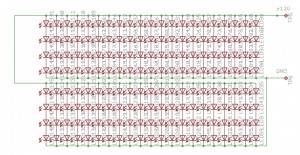
UV array schematic
The leds, grouped by four, can be powered with 12V directly, since the forwarding voltage of a UV led is 3.3-3.6V.
Actually, at 12V, they are a little bit underpowered, but I see this as a benefit. Even if exposure time is increased a little bit, a digital timer can do the trick and make a sound when the whole process is finished, leaving me to other tasks. For POSITIV 20 PCBs, the initial exposure time was quite strict, which annoyed me because at every error I had to clean the PCB, spray it, leave it to cure for 24 hours – basically every error ate one full day. Prolonging the exposure time to 1:30-2:00 minutes means more finesse and less time and materials and nerves lost.
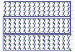
UV array PCB
The leds should be emitting somewhere around 380-400 nm and they can easily found very cheap on ebay. This array contains 168 UV leds.
B. Timer for the PCB exposure with Ultraviolet LEDs, with a Common Anode, 7 segments display
1. Schematic and PCB
The timer has at its heart an Atmel ATtiny2313 micro-controller that was hanging in a box, along with older and unused AT90S1200 and AT90S2313. These were disturbing me every time I looked into that box. Suddenly, I saw this small project as a challenge to try to return back to the community a few of the things I have learned, by making a small but easy-readable project which would also serve my purpose of retiring the old bulb.
ATtiny1200 was too small for the project, and AT90S2313 lacked one output at first glance.
I have decided then to use the ATtiny2313 to make a small yet effective schematic, compared to those found googling. It seems that little guy did its job well in the end.
The schematic:
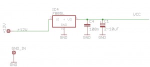
Power. Classical schematic with a 78L05, 5V linear regulator
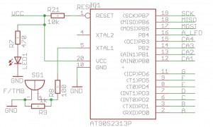
Micro-controller schematic
In the schematic, I have used AT90S2313, which is pin to pin compatible with ATtiny2313, excepting the XTAL lines. ATtiny2313 has a supplementary port, “A”, with three pins, with alternative functions on the XTAL and RESET pins. Two of the port A bits go to the XTAL pins if these are not used to drive a quartz and the third bit goes to the reset pin, if needed.
The buzzer has a 100 ohms resistor in series in order to limit the current drawn from the MCU pin, and a second, 1K, resistor, in parallel, in order to decrease the capacitive load of the buzzer (which is in fact a capacitor which sides are moving while powered). A led (red) shows that there is power. Another 10k resistor is tied to the RESET pin in order to keep it high while operating.
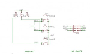
ISP header and keyboard schematic
The ISP header is tied to the MCU classically. The keyboard has just 3 keys, uses the same pins as the ISP and ties these pins to high level through 3 resistors, value 4.7 Kohms. I am using external resistors instead of the internal pull-ups because the internal pull-up resistors have, in my opinion, a too high resistance: 20-50 kohms for I/O pins and 30-60 kohms for the RESET pin.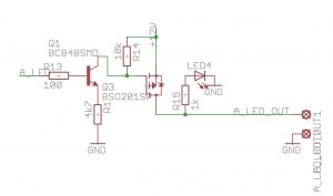
The power driver for the UV leds
The UV leds are driven by a p-channel mosfet, which is driven by an npn transistor which is driven by the MCU itself. The npn transistor is necessary to shift the 0-5V from the MCU output to an 8-12V output, necessary to drive the gate of the mosfet. I use p-channel mosfets usually because they allow me to keep a common ground between the driver and the load, as opposed to n-channel mosfets. A blue led is the witness on the PCB, to know the UV leds are lit. It is wired in parallel with the whole UV led matrix and it is powered by the mosfet itself.
The p-channel mosfet is enough to drive a steady load of 4.5A at 30V. This is enough for driving directly a load composed of 200 leds powered at 12V, and even more if using PWM.
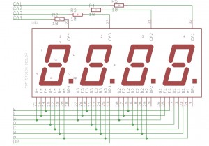
Common Anode Display Schematic
The display is a common anode one, found in another box, not multiplexed. I have tied all the segment outputs together to make it multiplexed. The display is tied directly to the MCU without using any transistors. Common anodes have 10 ohms resistors in series, to lower the current that passes through the display, without dimming it too much. A regular ATtiny2313 can withstand easily the current going through the display and just gets a little bit warmer while operating.
Actually, there is an error in the footprint of the display: the segments f and g are swapped, it was my error in the footprint design in Eagle. This mistake was solved in software, swapping f and g segments one more time.
If you wish to see the dot point (DP) blinking, to easier differentiate minutes from seconds, just wire the second DP pin to the ground. In the schematic and on the PCB this pin is in the air.
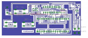
UV Timer PCB
The PCB is one-sided and contains just 8 straps and 1 wire wrapping for the Dot Point.
2. How it works – software
What can be learned from this small project:
- How to program several bits of a port as outputs and the others as inputs;
- How to use multi-dimensional data structures;
- How to program an Atmel MCU timer along with the prescaler in order to have
well-timed repetitive events;
- How to use an Atmel MCU interrupt routine;
- How to implement a power saving system to preserve our planet from useless
energy consumption and also to cool down electronic parts by diminishing
the load while in stand-by;
- How to set a particular bit in a port and how to clear a particular bit in
a port;
- How to make software timers;
- How to use bit value macros;
- How to read keys and avoid over-reads by using small delays;
- How to reuse pins in an MCU project;
- How to use functions in order to have very small, but intelligible main
routines;
- How to read and write from/to EEPROM;
- how to alter default values for direct usage upon power-up.
Just read the code, it is in my opinion very readable and self-explainable,
even for a newbie.
Operation:
When powered, the display shows in minutes and seconds a predefined value of 5:00. The display is blinking, showing that it is ready to be either programmed, or to start counting.
This value may be modified using the left and right keys (to decrease or to increase the timer). The steps are measured in seconds. The maximum value that can be programmed is 99 minutes and 59 seconds, just as much as the display can hold with just 4 digits.
To memorize in EEPROM the actual value, press LEFT and RIGHT keys simultaneously. At the next power-up, this will be the value used by default for countdown.
When pressing the “GO” key, the system:
– lits the UV leds and the witness blue led;
– starts counting downwards, to 0:00
– the display is not blinking anymore, nor is it shut
At the end of the countdown, the UV lights are shut, the display is blinking again and emits 10 beeps to let the user know it has terminated its job.
To save power and to allow the 78L05 regulator to cool down, the display is shut off after 10 seconds and just the dot point remains blinking.
I can assure you the 78L05 will function very well over time. However, if you feel any doubt, replace it with a 7805 and a small aluminum heat sink.
Any key will do exactly as intended and, if pressed, will disable the power down phase.
During power down, a beep is emitted every ~10 seconds to let the user know the device is waiting, asleep.
The code is written in C and compiles under AVR Studio 4.
The fuses for ATtiny2313 are set as follows:
SELFPREGEN - disabled
DWEN       - disabled
EESAVE     - disabled
SPIEN      - enabled
WDTON      - disabled
BODLEVEL   - brown-out detection disabled
RSTDISBL   - disabled
CKDIV8     - disabled
CKOUT      - disabled
SUT_CKSEL  - Internal RC Oscillator 8MHz; Start-up time: 14CK + 65 ms
The code:
#include <avr/io.h>
#include <avr/interrupt.h>
#include <avr/eeprom.h>
#define F_CPU 80000000
#include <util/delay.h>

#define SEG_a 0x01
#define SEG_b 0x02
#define SEG_c 0x04
#define SEG_d 0x08
#define SEG_e 0x10
#define SEG_f 0x20
#define SEG_g 0x40
#define SEG_dot 0x80

uint16_t EEMEM Edigit=800;
uint16_t Def_digit=300;

//global variables for isr()
uint16_t digit, decimal, digit_addressed=0;
uint8_t d[8];
uint8_t pulsing=0;
uint16_t pulseinterval;
uint16_t maxpulseinterval=512;
uint16_t ProgrammedDigit=0;
uint8_t LedOn=0;

//keys definition
#define GO        7
#define RIGHT     6
#define LEFT     5
#define KPIN  PINB
uint8_t keypressed=1;        //a key was pressed
uint8_t t1=0;
uint8_t Powersave=0;

//character definition
unsigned char seg[]=
{
    (SEG_a|SEG_b|SEG_c|SEG_d|SEG_e|SEG_g),             // 0
    (SEG_b|SEG_c),                                     // 1
    (SEG_a|SEG_b|SEG_d|SEG_e|SEG_f),                 // 2
    (SEG_a|SEG_b|SEG_c|SEG_d|SEG_f),                 // 3
    (SEG_b|SEG_c|SEG_c|SEG_f|SEG_g),                 // 4
    (SEG_a|SEG_c|SEG_d|SEG_f|SEG_g),                 // 5
    (SEG_a|SEG_c|SEG_d|SEG_e|SEG_f|SEG_g),             // 6
    (SEG_a|SEG_b|SEG_c),                             // 7
    (SEG_a|SEG_b|SEG_c|SEG_d|SEG_e|SEG_f|SEG_g),     // 8
    (SEG_a|SEG_b|SEG_c|SEG_d|SEG_f|SEG_g),             // 9
    (SEG_dot),                                             // NULL DISPLAY FOR POWER SAVE
};

//interrupt routine for character display
ISR(TIMER0_OVF_vect)
{
    pulseinterval++;
    if (pulseinterval>maxpulseinterval) pulseinterval=0;
    if ((pulsing==1) && (pulseinterval < maxpulseinterval/2))
    {
        PORTB=(0<<DDB0) | (0<<DDB1)| (0<<DDB2)| (0<<DDB3);
    }
    else
    {
        PORTD = ~(d[digit_addressed]);
        switch (digit_addressed)
        {
            case 0: PORTB=(1<<DDB0) | (0<<DDB1)| (0<<DDB2)| (0<<DDB3);
            break;
            case 1: PORTB=(0<<DDB0) | (1<<DDB1)| (0<<DDB2)| (0<<DDB3);
            break;
            case 2: PORTB=(0<<DDB0) | (0<<DDB1)| (1<<DDB2)| (0<<DDB3);
            break;
            default:PORTB=(0<<DDB0) | (0<<DDB1)| (0<<DDB2)| (1<<DDB3);
        }
        if (LedOn==1) PORTB |= (1<<DDB4);
        digit_addressed++;
        if(digit_addressed>=4) digit_addressed=0;
    }
}

void display(void)
{
    uint8_t min, sec;
    if (Powersave!=1)
    {
        min=digit/60;
        sec=digit-min*60;

        //computing digits
        d[4]=min/10;
        d[5]=min-d[4]*10;
        d[6]=sec/10;
        d[7]=sec-d[6]*10;

        d[0]= seg[d[4]];
        d[1]= seg[d[5]];
        d[2]= seg[d[6]];
        d[3]= seg[d[7]];
    }
    else
    {
        d[0]= seg[10];
        d[1]= seg[10];
        d[2]= seg[10];
        d[3]= seg[10];
    }
}

void init(void)
{
    TCNT0 = 0x00 ;
    TCCR0B = 0x03; //prescaler of 64
    TIMSK = 0x02; //overflow irq req'd
    sei();

    DDRA =1;
    PORTA=7;

    PORTB|=_BV(0)|_BV(1)|_BV(2)|_BV(3)|_BV(4);
    DDRB |=_BV(0)|_BV(1)|_BV(2)|_BV(3);

    PORTD=0xff;
    DDRD =0xff;
    pulsing=1;                //pulsing
    pulseinterval=0;
    digit= eeprom_read_word(&Edigit);
    if (digit==0xFFFF)        //not programmed EEPROM
    {
        digit=Def_digit;
        eeprom_write_word(&Edigit, Def_digit);
    }

                    //set default value
    display();                //starting value
    ProgrammedDigit=digit;    //if there is no delay programming, that one is the default value of 240s

}

void beep(void)
{
    PORTA=7;
    _delay_ms(10);
    PORTA=6;
    _delay_ms(30);

}

void readkeys(void)
{
    uint16_t i,j;
//LEFT AND RIGHT keys

//LEFT key
    if (bit_is_clear(KPIN, LEFT) && bit_is_clear(KPIN, RIGHT))
    {
        eeprom_write_word(&Edigit, digit);
    }
    else
    if bit_is_clear(KPIN, LEFT)
    {
        keypressed=1;
        digit--;
        if (digit==0xFFFF) digit=0;
        ProgrammedDigit=digit;
    }
    else
//RIGHT key
    if bit_is_clear(KPIN, RIGHT)
    {
        keypressed=1;
        digit++;
        if (digit>5999) digit=5999;
        ProgrammedDigit=digit;
    }
    else
        if bit_is_clear(KPIN, GO)
    {
        keypressed=1;
        Powersave=0;
        PORTA=7;
        _delay_ms(10);
        PORTA=6;
        _delay_ms(30);
        LedOn=1;
        pulsing=0;
        ProgrammedDigit=digit;
        for (i=0;i<ProgrammedDigit;i++)
        {
            _delay_ms(104);
            digit--;
            display();
        }
        digit=ProgrammedDigit;
        display();
        pulsing=1;
        LedOn=0;
        for(j=0; j<10; j++)
        {
            beep();
        }
        pulsing=1;
    }
    else    keypressed=0;

}

void testfordisplaysleep(void)
{
    if (keypressed==0)    //if there is no key pressed
    {
        t1++;
        if (t1==170)    //wait ~10 seconds
        {
            t1=0;
            beep();        //beep every ~10 seconds while sleeping
            Powersave=1;//and put display to sleep
        }
    }
    else                //on any key press
    {
        t1=0;
        Powersave=0;    //wake up display
    }
}

int main()

{
    init();
    _delay_ms(10);
    LedOn=0;
    PORTA=6;
    t1=0;
    keypressed=1;
    while(1)
    {
        readkeys();            //read key
        display();            //display number
        _delay_ms(6);        //wait a little bit
        testfordisplaysleep();
    }

}
The complete AVR4 project for the common anode display timer, without the EEPROM functionality, can be downloaded here.
In order to add this functionality to your project, copy and paste the code above over the UV_Timer.c file and recompile with AVR Studio 4.
3. The actual device
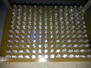
UV LED matrix
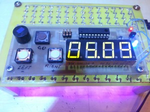
UV Leds and timer assembled
C. Timer for the PCB exposure with Ultraviolet LEDs, with a Common Cathode, 7 segments display
1. Schematic and PCB
The schematic is similar to the first version:

5V Power stage

ATtiny2313 connections
Here, one modification was made: the DP from the display was tied to the A1 pin.

Keyboard and ISP connectors

Mosfet Power Stage

Common Cathode Display

PCB
2. Software
Basically the software is the same as the common anode version, with the following differences:
a. The multiplex routine in ISR works with a negative logic, because of the common cathode. Digits definitions are also updated to the same negative logic. How does it work: we don’t lit anymore the segments to be lit, but we keep them off and lit all the other segments. Because of the polarity reversal on the display, our negative logic is inverted one more time. The result is that the segments defined to be off will in fact lit, leading to a positive image in the end.
b. Supplementary lines were added to solve the issue of the dot point. Since all dot points are wired together, the simpler solution used previously cannot be applied anymore. I have used the A1 bit of the ATtiny2313 to cope with the dot point. This bit must also be part of the multiplex routine, since we wish to lit only the second dot point and keep all other dot points off. Moreover, the A0 bit is used for activating the buzzer in all phases of the display: while on, blinking or in power save mode. This required the usage of specific bit processing while multiplexing. I’ll let you discover in the code the usage of specific bit processing, i.e. “setting the bit” and “clearing the bit”, while all the other bits remain unchanged.
The code:
#include <avr/io.h>
#include <avr/interrupt.h>
#include <avr/eeprom.h>
#define F_CPU 80000000
#include <util/delay.h>

#define SEG_a 0x01
#define SEG_b 0x02
#define SEG_c 0x04
#define SEG_d 0x08
#define SEG_e 0x10
#define SEG_f 0x20
#define SEG_g 0x40
#define SEG_dot 0x80

uint16_t EEMEM Edigit=800;
uint16_t Def_digit=300;

//global variables for isr()
uint16_t digit, decimal, digit_addressed=0;
uint8_t d[8];
uint8_t pulsing=0;
uint16_t pulseinterval;
uint16_t maxpulseinterval=512;
uint16_t ProgrammedDigit=0;
uint8_t LedOn=0;

//keys definition
#define GO        7
#define RIGHT     6
#define LEFT     5
#define KPIN  PINB
uint8_t keypressed=1;        //a key was pressed
uint8_t t1=0;
uint8_t Powersave=0;

//character definition
unsigned char seg[]=
{
    //negative logic
    (SEG_g),                                         // 0
    (SEG_a|SEG_d|SEG_e|SEG_f|SEG_g),                // 1
    (SEG_c|SEG_f),                                     // 2
    (SEG_e|SEG_f),                                     // 3
    (SEG_a|SEG_d|SEG_e),                             // 4
    (SEG_b|SEG_e),                                     // 5
    (SEG_b),                                         // 6
    (SEG_d|SEG_e|SEG_f|SEG_g),                        // 7
    (SEG_dot),                                         // 8
    (SEG_e),                                         // 9
    (SEG_a|SEG_b|SEG_c|SEG_d|SEG_e|SEG_f|SEG_g)     // NULL DISPLAY FOR POWER SAVE
};

//interrupt routine for character display
ISR(TIMER0_OVF_vect)
{
    pulseinterval++;
    if (pulseinterval>maxpulseinterval) pulseinterval=0;
    if ((pulsing==1) && (pulseinterval < maxpulseinterval/2))
    {
        PORTB=(1<<DDB0) | (1<<DDB1)| (1<<DDB2)| (1<<DDB3);
    }
    else
    {
        PORTD = ~(d[digit_addressed]);

        switch (digit_addressed)
        {
            case 0: {PORTB=(0<<DDB0) | (1<<DDB1)| (1<<DDB2)| (1<<DDB3); PORTA=PORTA&~_BV(1);}     //clear bit 1 port a
            break;
            case 1: {PORTB=(1<<DDB0) | (0<<DDB1)| (1<<DDB2)| (1<<DDB3); PORTA|=_BV(1);}         //set   bit 1 port a
            break;
            case 2: {PORTB=(1<<DDB0) | (1<<DDB1)| (0<<DDB2)| (1<<DDB3); PORTA=PORTA&~_BV(1);}    //clear bit 1 port a
            break;
            default:{PORTB=(1<<DDB0) | (1<<DDB1)| (1<<DDB2)| (0<<DDB3); PORTA=PORTA&~_BV(1);}    //clear bit 1 port a
        }
        if (LedOn==1) PORTB |= (1<<DDB4);
        digit_addressed++;
        if(digit_addressed>=4) digit_addressed=0;
    }
}

void display(void)
{
    uint8_t min, sec;
    if (Powersave!=1)
    {
        min=digit/60;
        sec=digit-min*60;

        //computing digits
        d[4]=min/10;
        d[5]=min-d[4]*10;
        d[6]=sec/10;
        d[7]=sec-d[6]*10;

        d[0]= seg[d[4]];
        d[1]= seg[d[5]];
        d[2]= seg[d[6]];
        d[3]= seg[d[7]];
    }
    else
    {
        d[0]= seg[10];
        d[1]= seg[10];
        d[2]= seg[10];
        d[3]= seg[10];
    }
}

void init(void)
{
    TCNT0 = 0x00 ;
    TCCR0B = 0x03; //prescaler of 64
    TIMSK = 0x02; //overflow irq req'd
    sei();

    DDRA =3;
    PORTA=_BV(0)|_BV(1)|_BV(2);    //all 3 bits of PORT A are set -> DP lit, beep on
    PORTB|=_BV(0)|_BV(1)|_BV(2)|_BV(3)|_BV(4);
    DDRB |=_BV(0)|_BV(1)|_BV(2)|_BV(3);

    PORTD=0xff;
    DDRD =0xff;
    pulsing=1;                //pulsing
    pulseinterval=0;
    digit= eeprom_read_word(&Edigit);
    if (digit==0xFFFF)        //not programmed EEPROM
    {
        digit=Def_digit;
        eeprom_write_word(&Edigit, Def_digit);
    }

                    //set default value
    display();                //starting value
    ProgrammedDigit=digit;    //if there is no delay programming, that one is the default value of 240s

}

void beep(void)
{
//    PORTA=7;
    PORTA|=_BV(0);            //enable beep
    _delay_ms(10);
//    PORTA=6;
    PORTA=PORTA& ~_BV(0);    //disable beep
    _delay_ms(30);

}

void readkeys(void)
{
    uint16_t i,j;
//LEFT AND RIGHT keys

//LEFT key
    if (bit_is_clear(KPIN, LEFT) && bit_is_clear(KPIN, RIGHT))
    {
        eeprom_write_word(&Edigit, digit);
    }
    else
    if bit_is_clear(KPIN, LEFT)
    {
        keypressed=1;
        digit--;
        if (digit==0xFFFF) digit=0;
        ProgrammedDigit=digit;
    }
    else
//RIGHT key
    if bit_is_clear(KPIN, RIGHT)
    {
        keypressed=1;
        digit++;
        if (digit>5999) digit=5999;
        ProgrammedDigit=digit;
    }
    else
        if bit_is_clear(KPIN, GO)
    {
        keypressed=1;
        Powersave=0;
//        PORTA=7;
        PORTA=_BV(0)|_BV(1)|_BV(2);
        _delay_ms(10);
//        PORTA=6;
        PORTA=_BV(1)|_BV(2);
        _delay_ms(30);
        LedOn=1;
        pulsing=0;
        ProgrammedDigit=digit;
        for (i=0;i<ProgrammedDigit;i++)
        {
            _delay_ms(100);
            digit--;
            display();
        }
        digit=ProgrammedDigit;
        display();
        pulsing=1;
        LedOn=0;
        for(j=0; j<10; j++)
        {
            beep();
        }
        pulsing=1;
    }
    else    keypressed=0;

}

void testfordisplaysleep(void)
{
    if (keypressed==0)    //if there is no key pressed
    {
        t1++;
        if (t1==170)    //wait ~10 seconds
        {
            t1=0;
            beep();        //beep every ~10 seconds while sleeping
            Powersave=1;//and put display to sleep
        }
    }
    else                //on any key press
    {
        t1=0;
        Powersave=0;    //wake up display
    }
}

int main()

{
    init();
    _delay_ms(10);
    LedOn=0;
    PORTA=_BV(1)|_BV(2);    //turn off beep, keep DP lit
    t1=0;
    keypressed=1;
    while(1)
    {
        readkeys();            //read key
        display();            //display number
        _delay_ms(6);        //wait a little bit
        testfordisplaysleep();
    }

}
The complete AVR4 project for the common cathode display timer can be downloaded here.
In order to add this functionality to your project, copy and paste the code above over the UV_Timer.c file and recompile with AVR Studio 4.
The Mosfet used in this project were both 9435 P-channel enhanced mode (30V/4A) Mosfets. The first version used a SOP-8 capsule while the second project used a TO-252 capsule. Since Eagle has parts with the same capsule and pin assignment for other parts, I have found uninteresting to make a library just for 9435. The datasheet for 9435 can be downloaded here.
3. The actual device
D. Timer for the PCB exposure with Ultraviolet LEDs, with a Common Cathode, 7 segments display and PWM
This is a further development of the the actual project in order to obtain a full-featured timer, and it is the subject of this post.


